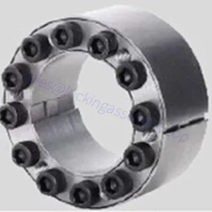
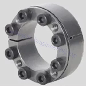
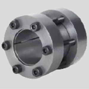
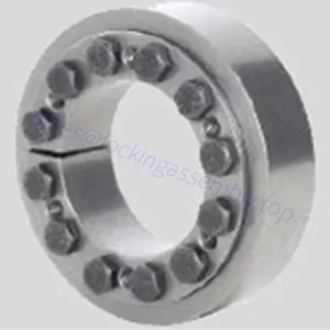
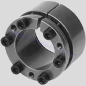
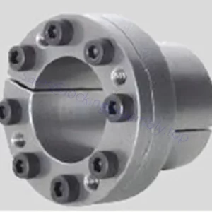
ep

2021-03-05

Connecting Website link – Press Fit (BS/DIN/ANSI)
The normal connecting link for ANSI series detachable chains, also utilised on riveted chains in which substantial speeds or arduous circumstances are encountered. Supplied with two connecting pins riveted in to the outer plate, another outer plate currently being a press fit onto the pins and secured by split pins right after assembly. Press match connecting links can only be utilised when; new links will have to always be used to replace dismantled links.
Cranked back links
Other than the specialized chains wherever the cranked hyperlink is definitely an vital style and design feature, cranked links are made use of only exactly where the chain length need to be an odd variety of pitches. This practice isn’t proposed; all drives should really, wherever feasible, be built with ample overall adjustment to make certain using an even number of pitches during the chain. Tend not to USE CRANKED Links ON IMPULSIVE, Hugely LOADED OR Large Speed DRIVES.
Cranked Website link – Slip Fit (BS/DIN) Offset Website link – Slip Match (ANSI)
A single website link with cranked plates pressed onto a bush and roller assemble at the narrow finish. A clearance fit connecting pin (No. 128) is fitted at the broad end and it is secured by a split pin.
Cranked Hyperlink Double (BS/DIN) Two Pitch Offset Hyperlink (ANSI)
Double cranked backlinks can be found for most sizes and sorts of chain. The unit consists of an inner hyperlink (No. four), with cranked back links retained permanently in position by a riveted bearing pin. Screw operated extractors break chain by forcing the end softened bearing pins from the outer hyperlink plates. For other manufacturers of chain, the rivet swell have to initial be ground away.

ep

2021-03-05

Precision Roller Chain, Elements and Connecting Back links
The precision steel roller chain is really a remarkably efficient and versatile suggests of transmitting mechanical power, which, while in the discipline of industrial applications, has practically fully superseded all other kinds of chain previously applied.
Outer Website link – Press Fit (BS/DIN) Riveting Pin Website link – Press Fit (ANSI)
For use with all sizes and types of chain where optimum security is wanted. The hyperlink is supplied with bearing pins riveted into one outer plate. The other outer plate is surely an interference fit over the bearing pins, the ends of which ought to be riveted in excess of just after the plate is fitted. Press fit connecting hyperlinks ought to only be made use of after; new back links need to be made use of to exchange dismantled hyperlinks. (See ‘Riveting Chain Endless’ for complete instructions).
Connecting Website link – Slip Fit (BS/DIN/ANSI)
A connecting website link provided with two connecting pins riveted to the outer plate. The outer plate is often a clearance fit to the connecting pins and is secured in place by a split pin with the projecting finish of each connecting pin.
Connecting Website link – Slip Match (BS/DIN/ANSI)
Made use of on short pitch chains only. Provided with two connecting pins riveted to the outer plate, the clearance match connecting plate getting secured by way of a spring clip, No. 27, which snaps into the grooves while in the pins.

ep

2021-03-05

Precision Roller Chain, Elements and Connecting Hyperlinks
The precision steel roller chain is really a really productive and versatile signifies of transmitting mechanical electrical power, which, in the field of industrial applications, has pretty much fully superseded all other forms of chain previously applied. The illustration under demonstrates component components on the outer link and in the inner hyperlink of the uncomplicated roller chain. As illustrated, the precision steel roller chain includes a series of journal bearings held in exact relationship to each and every other by the constraining website link plates. Every single bearing includes a bearing pin and bush on which the chain roller revolves. The bearing pin and bush are case hardened to permit articulation beneath substantial pressures, and also to contend with all the load carrying pressures and gearing action imparted by means of the chain rollers. All chains are classified according to pitch (the distance in between the centers of adjacent bearing pins), roller diameter and width concerning inner plates. Collectively, these dimensions are known as the gearing dimensions, as they ascertain the form and width with the sprocket teeth.
Regular backlinks
The chain parts and connecting backlinks illustrated are only indicative with the forms available. Please refer on the appropriate product or service page for the parts related to person chains.
They’re complete assemblies for use with all sizes and types of chain. The unit consists of two inner plates pressed on on the bushes which carry the rollers. (Inner backlinks for use with bush chains have no rollers).

ep

2021-03-04

STAINLESS STEEL CHAIN
The consolidation of Viking Chains Group into
Connexus Industries has allowed the continuation from the VC Brand of Steel Chains. The VC Brand says high quality manufacturing method, and extended support life. This effective brand contains the next:
WELDED STEEL CHAIN
? Complete Press Fit Rivets
? Parallel Sidebar Holes
? Higher Excellent Material & Heat Treating
WELDED STEEL PLUS
? Welded flush on outside eliminates any
interference with sprockets
? Parallel holes for “True-Fit”
? Seamless Barrels eliminate
“Premature Stretch”
WELDED STEEL DRAG CHAIN
? Fully Heat Treated Barrels
? Complete Press Fit Rivets
? Parallel Sidebar Holes
? High Excellent Materials & Heat Treating
DOUBLE LENGTH INFEED CHAINS, SCANNING CHAINS, FLIGHTS, SPROCKETS AND BEDPLATES
? Specifically Constructed to withstand Substantial Speed, Impact applications
? Industry Leader for 25 plus years
? Custom Solutions
SUGAR MILL CHAINS
? Designed for Prolonged Service daily life in Sugar Mill applications
? Heat Treated Stainless Steel, Hard Chrome options available
? Standard and Custom attachments
SPECIALTY CHAINS FOR ALL MARKETS
Mill chain
I’Anco Cast alloy steel and Hadfield manganese steel mill chains are designed for the most severe services applications in wood processing facilities today. They are designed to handle extreme wear, substantial tensile loads and extreme impact. Our ability cast attachments integral to the link eliminates any chance of creating heat affected zones by welding; however, the materials are readily weldable allowing for quick turnaround times for custom attachments. All of our cast links have recessed head and rivet ends offering protection from side wear on the rivets. This also allows us to pour the links with heavier cross sections adding to the overall strength in the chains plus creating larger bearing surfaces to distribute the loads over a larger area reducing the wear on the side bars.

ep

2021-03-04

STAINLESS STEEL CHAIN
The consolidation of Viking Chains Group into
Connexus Industries has permitted the continuation with the VC Brand of Steel Chains. The VC Brand says quality manufacturing approach, and prolonged services life. This productive brand incorporates the following:
WELDED STEEL CHAIN
? Complete Press Fit Rivets
? Parallel Sidebar Holes
? Substantial Good quality Materials & Heat Treating
WELDED STEEL PLUS
? Welded flush on outside eliminates any
interference with sprockets
? Parallel holes for “True-Fit”
? Seamless Barrels eliminate
“Premature Stretch”
WELDED STEEL DRAG CHAIN
? Fully Heat Treated Barrels
? Complete Press Match Rivets
? Parallel Sidebar Holes
? Substantial High-quality Material & Heat Treating
DOUBLE LENGTH INFEED CHAINS, SCANNING CHAINS, FLIGHTS, SPROCKETS AND BEDPLATES
? Specifically Constructed to withstand Higher Speed, Impact applications
? Industry Leader for 25 plus years
? Custom Solutions
SUGAR MILL CHAINS
? Designed for Extended Support daily life in Sugar Mill applications
? Heat Treated Stainless Steel, Hard Chrome options available
? Standard and Custom attachments
SPECIALTY CHAINS FOR ALL MARKETS
Mill chain
I’Anco Cast alloy steel and Hadfield manganese steel mill chains are designed for the most severe service applications in wood processing facilities today. They are designed to handle extreme wear, large tensile loads and extreme impact. Our ability cast attachments integral to the link eliminates any chance of creating heat affected zones by welding; however, the materials are readily weldable allowing for quick turnaround times for custom attachments. All of our cast links have recessed head and rivet ends offering protection from side wear on the rivets. This also allows us to pour the links with heavier cross sections adding to the overall strength in the chains plus creating larger bearing surfaces to distribute the loads over a larger area reducing the wear on the side bars.

ep

2021-03-04

Stainless-steel CHAIN
Built for foods apps as well as in spots where by wash-down, steam, and
chemical substances are widespread.
DRAG CHAIN
Offer efficient usually means to convey.
sawdust, chips or bark dust. Prolonged
operate lifestyle in slow speed apps.
81X ENGINEERING Course CHAIN
Generally used for gradual to moderate speed drives and conveyor programs.
Typical attachments include things like bullnose UHMW, plastic caps, camelbacks,
trimmer lugs and pusher lugs.
AGRICULTURAL Course CHAIN
Designed to face up to the harsh
setting on the agriculture
marketplace. Long lasting, with considerably less
servicing.
LEAF CHAIN
Leaf chain is useful for purposes that require potent versatile linkage for transmitting movement or elevate.
Energy TRANSMISSION CHAIN
Built to deliver a flexible usually means of ability transmission. Accessible in both offset and straight sidebar configuration.
DOUBLE FLEX CHAIN
Intended for conveying applications the place bend radius is needed for material movement modify of direction.
SHARP Best CHAIN?
Fantastic remedy to extend feed speeds. Accessible in a lot of tooth profile designs. Number 1 option of primary tools manufacturers.
WELDED Steel MILL CHAIN
Especially developed to offer economical means to convey item in right now??¥s
most complicated product dealing with programs. Welded attachments are available in many variations.
ROLLER CHAIN
Great for industrial and agriculture apps. Plates and rollers are shot peened and pre-stretched at factory for greater strength and longer life.

ep

2021-03-04

SMR Reducer Specification
1, Output Hubs
Conventional or alternate hubs with metric bores can be found to suit international shaft diameters.
two, Precision Good quality Gearing
Pc Made Helical Gear. Sturdy Alloy Components for Higher Load Capacity, Case Carburized for extended daily life, Ground Profile (some intermediate pinions are shaved), Crown tooth Profile, In Conformance with ISO 1328-1997, 98% Efficiency for per Stage, Smooth Quiet Operation with Teeth in Mesh.
3, Highest Capacity Housing Layout
Close Grain Cast Iron Building, Great Vibration Dampening & shock Resistance features, Precision Bored and Dowelled to Ensure Accurate In-line Assembly.
4, Robust Alloy Steel Shafts
Robust Alloy Steel, Hardened, Ground on journals, Gear Seatings and Extensions, for Optimum Load and Highest Torsional Loads, Generous Sizes Shaft Keys for Shock Loading and Conform to ISO Standards.
5, Additional Situation Lugs (Except H and J Gear Case)
Eliminates the Need for Critical Tightening of Torque arm Bolts, Controls Position of Typical Torque Arm Mounting within Recommended limits.
6, Backstops
Alternate Parts, Anti-run Back Device, Are available on all 13:one and 20:1 Ratio units and do not recommend for 5:one Units.
7, Bearing and Oil seals
Bearing are Adequately Proportioned and Conform to ISO dimension plan, Readily Offered World-wide, Oil seals are Double.
Lipped Garter Spring Type, Ensuring Effective Oil Sealing.
8, Rubberised End Caps
Self sealing Intermediate Cover Plates, to Conventional ISO Housing Dimensions.
9, Torque Arm Assembly
For Easy Adjustment of the Belt.

ep

2021-03-03

SMR Reducer Specification
one, Output Hubs
Standard or option hubs with metric bores are available to suit global shaft diameters.
2, Precision Top quality Gearing
Laptop Made Helical Gear. Sturdy Alloy Components for Substantial Load Capacity, Case Carburized for prolonged lifestyle, Ground Profile (some intermediate pinions are shaved), Crown tooth Profile, In Conformance with ISO 1328-1997, 98% Efficiency for per Stage, Smooth Quiet Operation with Teeth in Mesh.
three, Greatest Capacity Housing Design and style
Shut Grain Cast Iron Development, Outstanding Vibration Dampening & shock Resistance features, Precision Bored and Dowelled to Ensure Accurate In-line Assembly.
4, Sturdy Alloy Steel Shafts
Strong Alloy Steel, Hardened, Ground on journals, Gear Seatings and Extensions, for Maximum Load and Highest Torsional Loads, Generous Sizes Shaft Keys for Shock Loading and Conform to ISO Standards.
5, Additional Situation Lugs (Except H and J Gear Case)
Eliminates the Need for Critical Tightening of Torque arm Bolts, Controls Position of Common Torque Arm Mounting within Recommended limits.
6, Backstops
Alternative Parts, Anti-run Back Device, Can be found on all 13:1 and 20:1 Ratio units and do not recommend for 5:one Units.
7, Bearing and Oil seals
Bearing are Adequately Proportioned and Conform to ISO dimension plan, Readily Obtainable World-wide, Oil seals are Double.
Lipped Garter Spring Type, Ensuring Effective Oil Sealing.
8, Rubberised End Caps
Self sealing Intermediate Cover Plates, to Common ISO Housing Dimensions.
9, Torque Arm Assembly
For Easy Adjustment of the Belt.

ep

2021-03-03

JDLB Characteristics
Servo worm gear units have six varieties :45 – 50 – 55 – 63 – 75 – 90, with dual lead worm drive. Left and appropriate flank of worm shaft utilizing distinct lead angle leading to tooth thickness gradual transform. To ensure that you are able to move worm shaft
and alter backlash.
JDLB Applications
Precision rotary motion
— Lowering the noise and vibration that’s induced from the load transform as well as
modify of cutting force.
— decreasing the noise and effect that is certainly brought on from the corotation and reverse.
— By cutting down worm abrasion.
— Rising worm output response pace.
Precision Indexing device
— CNC machine, assembly line, cutting machine, transmission lines, etc.
— Indexing gadget, exact reading mechanism demand accurate motion
occasions.
Pace shifting conditions.
— Lowering the noise as well as the effect that is certainly caused by velocity transform.
— Reducing the worm abrasion that is brought on by pace adjustments.
JDLB Make preference
The following headings include data on important aspects for
selection and proper utilization of gearbox.
For particular data around the gearbox array, see the pertinent chapters.
EFFICIENCY
Efficiency is often a parameter which includes a big influence about the sizing of specific applications, and generally depends on gear pair layout components.
The mesh information table on webpage 9 demonstrates dynamic efficiency (n1=1400)and static efficiency values.
Understand that these values are only achieved immediately after the unit continues to be run in and it is with the functioning temperature.

ep

2021-03-03

JDLB series substantial precision worm gear is definitely an excellent substitute for
precision planetary gearbox, the tools manufacturer can
considerably decrease the cost of utilizing precision planetary gearbox.
Hollow output with shrink disc, substantial precision, for straightforward integration.
Output with keyway, convenient installation, straightforward integration.
Sound shaft output (single, double), higher stiffness, common remedy.
The designer’s ideal option is usually to rotate 90 degrees to install the servo motor drive programs.
Worm shaft in series might be driven by 1 motor to realize synchronous output of various worm wheels. It’s been utilised in
automatic polishing mobile phone shell and also other equipments.
Optimized contact pattern
* Sophisticated processing engineering and precision assembly to ensure the right meshing from the tooth and decrease get hold of pressure on the tooth surface.
* Particular worm wheel bronze alloy can make the teeth have large strength and very good wear resistance.
* With a large ratio of tooth surface get in touch with, worm wheel just isn’t effortless to wear, it can preserve the locked backlash.
Optimized adjustment construction
* Swiftly setting backlash.
* Increased stiffness and precision.
* Patent structure.
Upkeep no cost
* Higher overall performance synthetic lubricant.
* Closed structure, no need to have to exchange lubricant oil.
Immediately set up servo motor
* Substantial stiffness and lower inertia coupling for servo motor.
* Many different flanges might be matched with the servo motor.
Set up two taper roller bearings with which have longer services lives.
* Eliminates worm shaft alignment challenges.
* Bearing pre-tight set up, with increased help stiffness.
Worm shaft utilizing Taper roller bearings.
* Set up two taper roller bearings with which have longer services lives.
* Eliminates worm shaft alignment problems.
* Bearing pre-tight set up, with larger support stiffness.
Output torsional backlash readily available in two ranges:
* Ultra precision: 1 arc minute for the most demanding applications.
* Precision: two to four arc minutes a superb compromise value and high-quality.
Housing with gravity casting
* Higher strength Aluminum Alloy casting and heat treatment method.
* Superior rigidity and minimal fat.
* Lovely form and Good climate resisting residence.

ep

2021-03-01

Fluid couplings
Attention:
the smallest dimension Dp belt tray can do. the largest size the dl axle hole can do YOXp type is usually a connection type of belt tray with hydraulic coincidence machine. The electromotive machine (or decelerating machine) axle right inserts in the axle hole from the coincidence machine and that is suitable in equipment transported by belt.
Customer have to supply the connection size of electromotive machine axle (d1 L1) and also the in depth specification and dimension of belt tray.
YOXm is one particular that the axle of decelerating machine right inserts during the axle hole of coincidence machine as well as electromotive machine point ML(GB5272-85) connects with plum blossom type elastic axle connecting machine.
It really is trusted linked and has simple structure, the smallest axle size that’s a common connection sort in recent small coincidence machine.
Customer ought to supply the dimension of electromotive machine axle (d1 L1) and decerating machine axle (d2 L2) as proven while in the image, other individuals if consumer usually do not provide, we will manufacture according for the sizes while in the table.
Attention:L while in the table may be the smallest axle dimension. If lengthen the L1,the total length of L will be extra.d1,d2are the largest dimension that we will do.
YOXf is actually a variety linked both sides, the axle size of that’s longer. However it has simple framework and it is more practical and simpler for repairing and amending (pointless to move the electromotive machine and decelerating machine but only the elastic pillar and connecting spiral bolt can unload the coincidence machine).
The related elastic axle connecting machine, connecting dimension and outer size is generally the identical with YOXe style.
Versatile Coupling Model is widely applied for its compact designing,easy installation,convenient maintenance,small size and light weight.As prolonged as there lative displacement concerning shafts is kept inside the specified tolerance,the coupling will
operate the ideal function in addition to a longer working life,thus it truly is tremendously demanded in medium and minor power transmission
techniques drive by motors,such as speed reducers,hoists,compressor,spining &weaving machines and ball mills,permittable
relative displacement: Radial displacement 0.2-0.6mm; Angel displacement 0o30′–1o30′

ep

2021-03-01

Fluid couplings
Attributes:
Increase the beginning capability of electric motor, guard motor towards overloading, damp shock, load
fluctuation and torsional vibration, and balance and load distribution in situation of multi motor drives.
Applications:
Belt conveyers, csraper conveyers, and conveyers of all varieties Bucket elevators, ball mills, hoisters, crushers,
excavators, mixers, straighteners, cranes, etc.
Assortment:
With no distinctive needs the following technical information sheet and power chart are employed to pick the correct dimension of
fluid coupling with oil medium according on the power transmitted along with the velocity of motor, e, i, the input with the fluid coupling.
When ordering, please specify the dimensions of the shaft ends of motor and driven machine(or reducer)which include
diameter, tolerance or fit of your shafts (if no tolerance or fit is specified, the bores will probably be machined the H7),fit length in the
shafts, width and depth with the keys (of observe the standard No. enforced).For ordering the fluid couplings with belt pulley, brake
pulley or the particular necessities please state the technical information in detail.
YOXz is really a coincidence machine with moving wheel that is during the output point in the coincidence machine
and it is connected with elastic axle connecting machine (plum blossom style elastic axle connecting machine or
elastic pillar axle-connecting machine or maybe the axle-connecting machine designated by prospects). Ordinarily
there are actually three connection forms.
YOXz is inner wheel driver which has tight framework and also the smallest axle dimension. The fittings of YOXz possess a wide
utilization, very simple framework and also the dimension of it has fundamentally be unified in the trade. The connection kind of YOXz is that
the axle size of it is actually longer but it is unnecessary to move the electromotive machine and decelerating machine. Only
demolish the weak pillar and linked spiral bolt can unload the coincidence machine so it is actually severe easy.
Consumer need to offer you the size of electromotive machine axle (d1 L1) and decelerating machine axle (d2 L2). The
wheel dimension (Dz Lz C) within the table is only for reference, the real size is made a decision by prospects.

ep

2021-03-01

Fluid couplings
Options:
Boost the beginning capability of electric motor, safeguard motor towards overloading, damp shock, load
fluctuation and torsional vibration, and balance and load distribution in case of multi motor drives.
Applications:
Belt conveyers, csraper conveyers, and conveyers of all kinds Bucket elevators, ball mills, hoisters, crushers,
excavators, mixers, straighteners, cranes, and so on.
Assortment:
Devoid of unique specifications the next technical data sheet and energy chart are utilised to select the proper size of
fluid coupling with oil medium according to the power transmitted plus the velocity of motor, e, i, the input of your fluid coupling.
When ordering, please specify the dimensions on the shaft ends of motor and driven machine(or reducer)which include
diameter, tolerance or match of the shafts (if no tolerance or fit is specified, the bores will probably be machined the H7),fit length on the
shafts, width and depth of your keys (of recognize the normal No. enforced).For ordering the fluid couplings with belt pulley, brake
pulley or the special needs please state the technical data in detail.
YOXz is a coincidence machine with moving wheel that is within the output level from the coincidence machine
and it is linked with elastic axle connecting machine (plum blossom kind elastic axle connecting machine or
elastic pillar axle-connecting machine and even the axle-connecting machine designated by shoppers). Generally
you can find 3 connection sorts.
YOXz is inner wheel driver which has tight framework as well as the smallest axle size. The fittings of YOXz have a wide
usage, simple construction and also the size of it’s generally be unified from the trade. The connection style of YOXz is the fact that
the axle size of it truly is longer nevertheless it is unnecessary to move the electromotive machine and decelerating machine. Only
demolish the weak pillar and connected spiral bolt can unload the coincidence machine so it truly is severe handy.
Consumer ought to give the dimension of electromotive machine axle (d1 L1) and decelerating machine axle (d2 L2). The
wheel size (Dz Lz C) within the table is just for reference, the actual size is decided by customers.

ep

2021-03-01

ROOTS VACUUM PUMPS
Operating Principle and Features: The series SYF roots vacuum pump is with overflow valve. The figure-of-eight rotors are counter-rotating at a continual speed within the pump housing for suction and exhaust of gasoline. Two rotors are supported by two bearings and synchronized by a gear, which ensures these two rotors in certain relative positions. They may be near to one another and to the housing with no actual contacting, so lubrication is unnecessary in the functioning housing. The cautiously balanced working elements and high precision bevel wheels ensue the pump be operated stably and constantly under the ailment of high-pressure variation. Dynamic seal element utilizes our patent technology and imported oil seals, the vibration amount of shaft within the shaft seals is controlled to significantly less than 0.02mm. A gravity valve is installed involving the suction and exhaust a part of the pump. The perform of your gravity valve is as follows, when the stress big difference involving the suction and exhaust aspect is over the weight on the valve, the valve opens instantly, which tends to make the stress difference normally retain inside a fixed controllable worth, the worth may be the allowable highest stress distinction to ensure the pump function ordinarily and so that in fact, the roots vacuum pump with overflow valve is actually a sort of overload self-protective pump. Series SYF roots vacuum pump with overflow valve has considerably greater velocity at relatively lower inlet strain and it really is possessed overload self-protective function. As it is actually a pump of dry clearance seal building, if a specific pumping velocity price 15 and an greatest vacuum have to be obtained, it is required to supply a decrease inlet stress for reducing the back movement, consequently, a pump should be backed in use, roots vacuum pump really should be began quickly right after its inlet strain reaches a permissible worth for economization. It is allow to select distinctive varieties of pump as the backing pump for factual needs, this kind of as oil seal pump and liquid ring vacuum pump. When pumping the gas containing substantial amount of vapor, the liquid ring vacuum pump may be the best backing pump.

ep

2021-03-01

SINGLE STAGE VACUUM PUMPS
110/220VAC Vacuum Pumps
Single stage vacuum pumps operate on 110 VAC or 220VAC. Picking the correct size pump from one.five cfm to 9 cfm depends upon your distinct application. These pumps 1 engineered especially to help you do your career more quickly and greater.
High efficiency-CFM rated as ?¡ãfree air displacement.?¡À150micron area rating. Hefty duty substantial torque motor-assures cold climate staring.
Low operating temperature-improve efficiency and vacuum.
Forced-feed lubrication design-help minimize operating temperature and far better Lubrication.
DUAL STAGE VACUUM PUMPS
110/220VAC Vacuum Pumps
Dual stage vacuum pumps operators on 110 VAC or 220VAC.State-of-the-art dual-stage design pulls deep vacuum to 50 microns. Design of those one.five,3,5,8,10,twelve CFM pump improvements establish about the performance-proven high quality attributes. No matter what your vacuum pump requirements, the proper pump will visit operate with you.
Dual stage design-second stage starts pumping at a reduce strain to pull a deeper greatest vacuum.
Stopping oil-returning design-prevents pump oil from currently being sucked to the program if a electrical power loss takes place.
Gas ballast-speeds evacuation and keeps oil cleaner. Substantial oil reservoir-lightweight and much better dilute corrosive contaminants.
ROTARY PISTON VACUUM PUMPS
The series HGL, HG pump is actually a type of single-stage and single-cylinder rotary piston vacuum pump. It truly is significantly enhanced series H rotary piston pump and contains 4 patents; its standard abilities possess a fantastic improvement. Rotary piston vacuum pump can be a type of vacuum manufacturing products suitable for pumping ordinary gases and condensable gases(when a fuel ballast made use of). The pump has to be fitted with proper equipment if gas is wealthy in oxygen, explosive, corrosive to ferrous metal, chemical reactive with vacuum pump oil. Operation principle present in operating principle graph: A rotary piston with slide valve across eccentric wheel driven by shaft inside the housing. Piston pole can slide and swing freely in arch track. The whole pump chamber is divided into chamber A and chamber B by piston. When shaft rotates the volume of chamber A and chamber B are altered repetitively, so that pumping objective could possibly be attained.

ep

2021-02-26

VACUUM PUMPS OF SPIRAL SLICE Kind Use scope The single stage oil cycle vacuum pumps of spiral slice type of series SYF and double stage oil cycle vacuum pumps of spiral slice style in the series of 2SYF are vital products for abstracting the gasoline from obturational container to acquire vacuum. The double stage vacuum pumps of spiral slice style of the series of 2SYF employed for abstracting to acquire vacuum once more around the basis of single stage pumps. It could possibly make the system achieve the highest stage vacuum. Attributes (one) The style of stopping oil-returning The passage of fuel admission is specially created to protect against the returning of pumps oil delivering the abstracted container and pipeline soon after the pumps prevent working. (2) The layout of environmental protection The design of built-in gadget of mist eliminating, and set oil-gas seperator about the vent, the two cope with the pollution of oil all through the course of exhausting effectively. (three) Aluminum alloy casing of electric machinery The electric machinery use aluminum alloy casing, it’s high efficiency of heat emission, and make sure long time regular operation continously, furthermore, it has improved visual appeal high-quality. (4) The design and style of integration The electrical machinery and pumps utilize the style of integration producing the items extra significant and reasonable. (five) Large commencing up second Our product models specially aiming with the atmosphere of very low temperature and electrical pressure. ensuring the machine commences normally at reduced temperature of winter surroundings(?Y-5??) and low electric stress(?Y180V).

ep

2021-02-25

Ever-Power Vacuum Pumps Co.,Ltd.
Producer of: Vacuum pumps of spiral slice kind, Rotary Piston vacuum pumps, Roots Vacuum pumps, Cas-Cooling Roots Vacuum pumps, Rotary Vane Vacuum Pumps, Water ring Vacuum Pumps, Reciprocating vacuum pumps and Vacuum valves and check values together with other relevant vacuum items and technique. Hangzhou Ever-Power Vacuum Pumps Co.,Ltd. We have now the strongest development means of vacuum pumps and vacuum gear technologic. Organization has sophisticated style, Superior equipment, the largest vacuum pumps test center in China, also has previously established the strict Q/C systemas per ISO9001 regular. You can find total 25 main series of vacuum equipment, Our merchandise are widely utilized in departments of metallurgical, setting up components, petroleum, environmental, proteion, chemical, medicine, textiles, meals, aerospae, electronic, energy, national defence industries and science investigation and so forth.
LIQUID (WATER) RING VACUUM PUMPS
Operating principle and functions: For the series SK, 2SK, YK and 2YK liquid ring vacuum pumps, multi-vane impeller is fixed eccentrically within the pump casing. Once the vanes rotate, the liquid during the casing forms a liquid ring that is certainly concentric with the pump casing beneath the centrifugal effect, the cubage among liquid and vanes possess a periodic modify, so the function of pumping be performed. Liquid ring vacuum pumps are on the characteristics of low vitality consumption and very low noise. They can be made use of to pump water vapor, inflammable and explosive gas too as ordinary gases. With specific products made use of for major components, they are able to also pump corrosive fuel. Suitable actuating medium or from time to time pumped medium is usually chosen as actuating liquids, so the pumps can virtually handle all broadly applied for light, chemical, foods, electrical electrical power and pharmaceutical industries, and so on.

ep

2021-02-24

Observing a number of principles for appropriate set up is important on the reliable and good operation of your gearbox or gear motor.
The principles set out here are intended as being a preliminary guidebook to choosing gearbox or gear motor. For powerful and appropriate set up, comply with the instructions offered inside the set up, utilize the maintenances guide for your gearbox offered from our income department.
Following is often a short outline of installation principles:
a) Fastening:
Place gearbox on a surface providing adequate rigidity. Mating surfaces need to be machined and flat.
Mating surfaces need to be inside of definite geometric tolerances (see guide). This is certainly in particular true of flange-mounted gearboxes with splined hollow shafts.
In applications that involve high radial loads at the output end, flange mounting is advisable for some gearbox sizes as this mounting can make utilization of the double pilot diameters supplied in these gearboxes.
Make sure the gearbox is suitable for your required mounting position.
Use screws of resistance class 8.eight and in excess of to secure the gearbox. Torque up screws to your figures
indicated from the relevant tables.
With transmitted output torque better than or equal 70% on the indicated M2max torque, and with
frequent motion reversals, use screws with minimum resistance ten.9.
Some gearbox sizes is usually fastened making use of both screws or pins. Of pin seated within the frame the gearboxes be at least 1.5 instances pin diameter.
b) Connections
Secure the connection elements to gearbox input and output. Tend not to tap them with hammers or equivalent equipment.
To insert these parts, use the support screws and threaded holes supplied to the shafts. Be sure to clean off any grease or protects from the shafts just before fitting any connection components.
Fitting hydraulic motors.
Be careful the O ring amongst motor flange and gearbox input flange when assembling. Set up the
hydraulic motor in advance of filling lube oil to the gearbox.
Connecting the hydraulic brake.
The hydraulic circuit ought to be such to make certain that brake is released instants just before gearbox starts and applied following gearbox has stopped. Test that pressure in the hydraulic line for brake release is at zero every time gearbox is stopped.
Path of rotation
Motors are linked towards the ideal electric or hydraulic circuit as outlined by their route of rotation.
When carrying out these connections, bear in mind that all gearboxes, no matter if within the in-line or proper angle layout, possess the exact same route of rotation both at input and output. For more specifics with the connection of electrical and hydraulic motors, see pertinent sections on this catalogue.

ep

2021-02-23

TF Style Flanges
Model TF flanges are made from exactly the same high-strength cast iron because the S flanges, but are built to accommodate the international conventional Taper Lock bushing for uncomplicated installation and elimination
TF Variety flanges allow for mounting the bushing to the front (hub) side of the flange
TF flanges can be found in sizes six by means of sixteen and can be used with any type of sleeve as pictured on page SF-5
TR Form Flanges
TR flanges are similar on the TF design, but enable to the Taper Lock Bushing to get mounted and removed from
the reverse or serration side with the flange
The restricted torque ratings on the Taper Lock Bushings allow TR flanges to only be made use of with EPDM or Neoprene sleeves
Diverse bushing sizes are utilised, so they have diverse highest bores compared to the TF flanges
Sizes six via 16 are available
Taper-Lock Bushings
The market common taper lock bushing is usually a split design allowing a compression match of the flange to the shaft without having set screws
The straightforward design and style tends to make the set up and removal quick even though the 8° taper grips tight and offers outstanding concentricity
A Lowered level of inventory might be accomplished because of the many other electrical power transmission parts that use Taper Lock Bushings for example: sheaves, sprockets, and pulleys
isn’t going to give the Taper-Lock Bushings themselves as they are broadly obtainable from other manufacturers

ep

2021-02-23

B Type Flange
Model B (bushed) flanges are manufactured of your same high-strength cast iron because the S flanges
B flanges are intended to accommodate the industry conventional bushing for easy set up and removal
B flanges can be found in sizes 6 by way of 16
Couplings
S-Flex couplings with B flanges (for use with bushings) are normally supplied with the two-piece E sleeve
The B design flanges is usually made use of with any of your sleeves pictured on SF-5, together with the exception in the Hytrel sleeve
B flanges might be utilized in combination with S Variety flanges
Bushings
Bushings have a split layout that make it possible for for any compression match for secure mounting on the flange towards the shaft without set screws
The bushing’s clamp like match generates a one-piece assembly to get rid of wobble, vibration, and fretting corrosion
Somewhat oversized or undersized shafts is often accommodated with the same safe grip
The style and design prevents possibly hazardous crucial drift on applications topic to pulsation or vibration
B flanges are bored to accept a bushing accommodating many bore sizes, hence cutting down inventory and expanding coupling versatility
Bushing bore availability could be observed in current listing rate books or from the Customer service Representative

ep

2021-02-23

S-Flex Sleeves
Versatile sleeves for S-Flex couplings can be found in three elements (EPDM, Neoprene, and Hytrel) and in three fundamental types: one particular piece solid, one-piece split, or two piece
JE, JN, JES and JNS Forms
JE and JN Type sleeves characteristic a one-piece solid design and style
JES and JNS Style sleeves function a one-piece split layout
JE and JES Variety sleeves are molded in EPDM materials
JN and JNS Variety sleeves are molded in Neoprene material
E and N Forms
E and N Style sleeves feature a two-piece style and design with retaining ring
E Kind sleeves are produced from EPDM materials and therefore are out there in sizes 5-16
N Type sleeves are produced from Neoprene materials and are available in sizes 5-14
Two piece sleeves are great for applications wherever little shaft separations inhibit the installation of a one particular piece sleeve
H and HS Forms
H and HS Form sleeves are intended for substantial torque applications, transmitting about 4 occasions as substantially power as an equivalent EPDM or Neoprene sleeve
Hytrel sleeves can be found within a one-piece reliable (H) or two-piece split (HS) development
Hytrel sleeves is often utilised only with S or SC flanges and can not be utilised with J or B flanges
Hytrel sleeves ought to not be utilized as direct replacements for EPDM or Neoprene applications
H and HS Form sleeves can be found for sizes 6-14 (sizes 13 and 14 are available in HS only)

ep

2021-02-22

Procedure
S-Flex Coupling Choice System
The variety system for determining the proper S-Flex coupling involves working with the charts shown to the following pages. There are actually three parts to become chosen, two flanges and a single sleeve.
Data important before a coupling may be chosen:
HP and RPM of Driver or running torque
Shaft size of Driver and Driven gear and corresponding keyways
Application or tools description
Environmental problems (i.e. severe temperature, corrosive problems, space limitations)
Actions In Selecting An S-Flex Coupling
Phase one: Establish the Nominal Torque in in-lb of the application by utilizing the following formula:
Nominal Torque = (HP x 63025)/RPM
Stage two: Working with the Application Services Issue Chart 1 select the support component which best corresponds for your application.
Step three: Calculate the Design and style Torque of the application by multiplying the Nominal Torque calculated in Stage one from the Application Support Issue determined in Phase two.
Design Torque = Nominal Torque x Application Support Factor
Stage four: Applying the Sleeve Effectiveness Data Chart two pick the sleeve material which best corresponds for your application.
Phase 5: Making use of the S-Flex Nominal Rated Torque Chart 3 find the acceptable sleeve materials column to the sleeve picked in Stage four.
Phase 6: Scan down this column for the 1st entry wherever the Torque Worth from the column is higher than or equal to the Layout Torque calculated in Step 3.
Refer to your highest RPM value with the coupling dimension to guarantee that the application necessities are met. If your highest RPM worth is less than the application requirement, S-Flex couplings are usually not advised for that application.
Note:
If Nominal Torque is much less than 1/4 with the coupling’s nominalrated torque, misalignment capacities are reduced by 1/2. After torque worth is found, refer to your corresponding coupling dimension inside the first column from the S-Flex Nominal Rated Torque Data Chart 3 .
Stage seven: Review the application driver/driven shaft sizes towards the optimum bore size out there about the coupling selected. If coupling max bore just isn’t large enough to the shaft diameter, pick the following largest coupling that will accommodate the driver/driven shaft diameters.
Step 8: Using the Item Assortment tables, come across the ideal Keyway and Bore size demanded and find the variety.

ep

2021-02-22

We provide versatile sleeve for S-Flex coupling in three designs: one-piece solid, one-piece split, and two-piece with retaining ring
The one-piece split design presents answers for applications with one of a kind needs the place smaller shaft separations inhibit the installation of a one-piece solid sleeve
Pre-molded teeth along the diameter of your sleeve engage with teeth in the coupling flanges
No clamps or screws are wanted to connect the flanges with all the flexible sleeve which securely lock collectively under torque for smooth transmission of energy
Torque is transmitted as a result of shear loading of the sleeve
All three sleeve components are really elastic which permits the S-Flex coupling to protect linked tools from harmful shock loading, vibration, and shaft misalignment
JE, JN, JES, JNS Sleeve Sorts
These sleeves characteristic a one-piece design molded in EPDM & Neoprene rubber. In the case of JES & JNS Forms, the one-piece design is split to provide for ease of set up and removal.
E, N Sleeve Styles
These sleeves function a two-piece style and design with retaining ring. The E Type is molded in EPDM rubber and the N Type is molded in Neoprene. The two-piece design is ideal for applications where there is difficulty in separating the shafts in the driver and driven.
H, HS Sleeve Kinds
These sleeves characteristic both a one-piece solid (H) and two-piece split
(HS) layout and are molded of Hytrel. The sleeves in Hytrel material are designed to transmit energy for high torque applications. Because in the layout and the properties of your Hytrel molded sleeve, the H and HS sleeves should not be used as direct replacements for EPDM or Neoprene sleeves, and can only be used with S, TF, or SC flanges.
Sleeve Supplies
EPDM ?§C Unless otherwise specified, S-Flex couplings are supplied with EPDM versatile sleeves. EPDM has good resistance to commonly used chemicals and is generally not affected by dirt or moisture. Color is black.
NEOPRENE ?§C Neoprene gives very good performance characteristics for most applications and offers a very good resistance to chemical and oil conditions. Color is black with a green dot.
HYTREL ?§C Hytrel is a polyester elastomer designed for high torque and high temperature applications and offers excellent resistance to chemical and oil conditions. Color is orange.

ep

2021-02-22

Elastomer In Shear Variety Couplings
The straightforward style on the S-Flex coupling guarantees ease of assembly and dependable efficiency. No exclusive resources are necessary for installation or elimination. S-Flex couplings could be utilized in a wide variety of applications.
Functions
Easy to install
Maintenance Free
No Lubrication
Dampens Vibration and Controls Shock
Torsionally Soft
Double Engagement
Traits and Efficiency Details
The S-Flex coupling style is comprised of 3 components: two flanges with inner teeth engage an elastomeric flexible sleeve with external teeth
Torque is transmited as a result of the flanges mounted on both the driver and driven shafts by means of the sleeve
Misalignment and torsional shock loads are absorbed by shear deflection in the sleeve
The shear characteristic from the S-Flex coupling is quite very well suited to soak up impact loads
The S-Flex coupling provides combinations of flanges and sleeves which can be assembled to fit your specific application
Thirteen sizes are available with torque abilities that range from 60 in-lbs to 72,480 in-lbs
The S-Flex flanges are offered in 5 designs that are created from zinc or cast iron
Sleeves can be found in EPDM rubber, Neoprene to tackle a wide range of application specifications
Protection from misalignment, shock, and vibration:
PARALLEL:
The S-Flex coupling accepts up to .062 in of parallel misalignment with out wear. The versatile coupling sleeve minimizes the radial loads imposed on tools bearings, an issue frequently associated with parallel misalignment.
AXIAL:
The S-Flex couplings may be used in applications which call for a restricted level of shaft end-float without the need of transferring thrust loads to tools bearings. Axial motion of somewhere around 1/8 inch accepted.
ANGULAR:
The flexing action of the elastomeric sleeve as well as the locking characteristic in the mating teeth enables the S-Flex coupling to proficiently handle angular misalignment up to 1??.
TORSIONAL:
S-Flex couplings proficiently dampen torsional shock and vibration to guard linked gear. The EPDM and Neoprene sleeves have torsional wind-up flexibility of 15?? at their rated torque. Hytrel presents 7??wind-up.

ep

2021-02-20

H Form Couplings
The H Style coupling includes two hubs, two within sleeves, one particular cushion set and a single collar with hardware. H Variety coupling hubs are provided with an inside sleeve. For technical help, please make contact with Lovejoy Engineering.
Capabilities
Better torque and bore capability compared to the C-Line series jaw coupling
Elastomeric cushions are radially removable
Cushions accessible in SXB rubber and Hytrel
RRC Variety Radially Removable Spacer Coupling
RRC Sort couplings range from sizes RRC226to RRC2955.
The RRC Form coupling includes:
2 RRC Hub Adapters (involves bolts)
one Spacer assembly consisting of:
2 RRC Jaw rings
1 collar with hardware
one set of SXB (NBR) cushions

L Type Coupling
Sizes assortment from L035 to L276
Ordering requires selecting UPC numbers for two normal L hubs and 1 standard open or strong center elastomer (spider)

SW Variety Coupling
Sizes variety from L090 to L190
Ordering demands picking UPC numbers for two common L hubs and 1 snap wrap spider with snap ring
Both L and SW Type couplings, select hubs from your typical bore and keyway chart (pages JW-11 and JW-12) maximum RPM for SW + Ring is one,750 RPM
LC coupling employs a snap wrap spider by using a collar as a substitute of a retaining ring
Jaw In-Shear Coupling
Ordering calls for choosing item numbers for two regular hubs, one In-Shear elastomer and a single In-Shear ring.

ep

2021-02-20

C Type Couplings
The C Form coupling includes two common hubs, one particular cushion set and collar with hardware.
Options
Higher torque and bore capability than the L-Line series jaw coupling
Elastomeric cushions are radially removable
Cushions obtainable in SXB rubber and Hytrel

RRS and RRSC Kind Radially Removable Spacer Couplings
RRS Variety couplings assortment from sizes RRS090 to RRS225. The RRS Style
coupling consists of:
RRS090 – RRS110:
2 Normal RRS Hubs
one Spacer Assembly consisting of:
two snap wrap spiders w/o ring
2 collars with screws
1 spacer
RRS150 – RRS225:
one Regular RRS Hub
one Normal RRSC Hub – Drilled for collar
1 Spacer Assembly consisting of:
two snap wrap spiders w/o ring
2 collars with screws
1 spacer
Note:
RRS Type Inch Hubs provided typical with two set screws at 90°.
Capabilities
Typical API primarily based spacers offered
Radially removable inserts
Common Lovejoy hub style and design with additional set screw at 90°

ep

2021-02-20

The LC Kind coupling includes one particular regular L Style hub (without the need of collar attachment), one LC Type hub (delivers collar attachment), one common snap wrap center and a single collar with screws. Features
Radially removable insert
Collar enables for optimum speed of 3,600 RPM
Collar manufactured from 1018 Steel
Notes:
These “LC” hubs are drilled and tapped to accept collar mounting screws but the collar and hardware are certainly not included.
See L Form (inch or metric) coupling chart for standard hub.
Tolerances for bore and keyways are uncovered in Engineering Data part .
All hubs are supplied standard with 1 set screw.
When referencing the quantity in this table, incorporate 685144 being a prefix to the quantity shown.
AL and SS Variety Couplings
The AL Style coupling includes two hubs and 1 spider.
Functions
Interchangeable with all hub sizes standard for the L-Line and AL-Line items
Readily available within a variety of different finished bore and keyway combinations
Finished bores passivated for additional rust safety
AL Style Couplings
The AL Type coupling consists of two hubs and one particular spider.
Options
Aluminum material is corrosion resistant
Lightweight
Hubs compatible with standard Lovejoy hub style and design (except AL150)

ep

2021-02-19

Jaw Type Coupling Variety Process
The variety approach for determining the proper jaw coupling size and elastomer demands using the charts shown about the following pages. You will find three parts to get chosen, two hubs and a single elastomer. Once the shaft size with the driver and driven in the application are of your exact same diameter, the hubs chosen will probably be the same. When shaft diameters differ, hubs chosen will differ accordingly.
Facts required ahead of a coupling is often picked:
HP (or KW) and RPM or Torque of driver
Shaft sizes of driver and driven products and corresponding keyways
Application description
Environmental circumstances (i.e. intense temperature, corrosive ailments, room limitations)
Ways In Choosing A Jaw Coupling
Step one: Identify the Nominal Torque of one’s application by utilizing the following formula:
Nominal Torque = in-lb = (HP x 63025)/RPM
Nm = (KW x 9550)/RPM
Step two: Employing the Application Services Aspects Chart 1 pick the service factor which very best corresponds for your application.
Stage 3: Calculate the Design and style Torque of one’s application by multiplying the Nominal Torque calculated in Stage one from the Application Support Issue established in Stage two.
Design and style Torque = Nominal Torque x Application Services Issue
Phase four: Employing the Spider Overall performance Data Chart 2, pick the elastomer materials which very best corresponds for your application.
Step 5: Utilizing the Jaw Nominal Rated Torque Chart 3 , find the proper elastomer materials column for your elastomer picked in Phase 4.
Scan down this column for the first entry where the Torque Value within the suitable column is higher than or equal to the Design Torque calculated in Step 3.
As soon as this worth is located, refer for the corresponding coupling dimension within the initial column of the Jaw Nominal Rated Torque Chart three .
Refer on the greatest RPM worth for this elastomer torque capability to guarantee the application needs are met. In case the requirement just isn’t happy at this time, a different variety of coupling can be required for your application. Please seek the advice of Lovejoy engineering for assistance.
Stage six: Compare the application driver/driven shaft sizes on the highest bore dimension accessible about the coupling picked. If coupling bore dimension just isn’t significant sufficient for your shaft diameter, decide on the following greatest coupling that may accommodate the driver/driven shaft diameters.
Stage 7: Employing the UPC variety variety table , find the appropriate Bore and Keyway sizes necessary and find the quantity.

ep

2021-02-19

Elastomers In Compression
We features 4 sorts of elastomer models to permit for added versatility in addressing specific application necessities. A single piece patterns are used in the “L” and “AL” versions (referred to as spiders) and several portion “load cushions” are used in the “C” and “H” model couplings. The load cushions are in sets of six to 14 pieces according to coupling size.
Reliable Center Spider
The reliable center layout is frequently made use of style and design when shafts from the driver and driven tools may be kept separate by a regular gap
Open Center Spider
The open center design and style makes it possible for for that shafts from the driver and driven to become positioned inside a brief distance
Open center spiders offer you shaft positioning flexibility but have a decrease RPM capacity
Cushions
Utilised exclusively for the C and H Form couplings
Load cushions are held in area radially by a steel collar which is connected to one of the hubs
Snap Wrap Versatile Spider
Layout lets for straightforward elimination on the spider without the need of moving the hubs
Will allow for close shaft separation the many way up to the hubs highest bore
Highest RPM is 1,750 RPM together with the retaining ring, but when utilized together with the LC Style (with collar) the regular RPM rating in the coupling applies
Type is available in NBR and Urethane only, and in constrained sizes
Spider Resources
SOX (NBR) Rubber
The standard materials which is highly versatile materials that is definitely oil resistant
Resembles pure rubber in resilience and elasticity, and operates successfully in temperature ranges of -40° to 212° F (-40° to 100° C)
Urethane
Has one.5 instances greater torque capacity than NBR
Very good resistance to oil and chemicals
Materials gives less dampening impact and operates at a temperature choice of -30° to 160° F
Hytrel
Flexible elastomer made for higher torque and higher temperature operations
Operates in temperatures of -60° to 250° F (-51° to 121° C)
Bronze
Rigid, porous, oil-impregnated metal insert solely for very low pace (max 250 RPM) applications requiring higher torque capabilities
Not affected by water, oil, grime, or severe temperatures – operates in temperatures of -40° to 450° F (-40° to 232° C)

ep

2021-02-19

The Jaw Form couplings are supplied while in the industry?¡¥s largest selection of stock bore/keyway combinations. These couplings call for no lubrication and present highly trusted services for light, medium, and hefty duty electrical motor and internal combustion power transmission applications.
Features
Fail-safe ¡§C will nonetheless execute if elastomer fails
No metal to metal get hold of
Resistant to oil, grime, sand, moisture and grease
More than 850,000 combinations of bore sizes
Most kinds readily available from stock in 24 hrs
Applications consist of power transmission to industrial products like pumps, gear boxes, compressors, blowers, mixers, and conveyors. Jaw Sort couplings can be found in 24 sizes from a minimum torque rating of three.5 in¡§Clbs to a maximum torque rating of 170,004 in¡§Clbs and a bore range of .125 inches to seven inches.Our typical bore system covers AGMA, SAE, and DIN bore/keyway and spline bore combinations.
The Jaw Sort coupling is obtainable within a variety of metal hub and insert materials. Hubs are offered in sintered metal, aluminum, bronze, steel, stainless steel, and ductile iron.
L Style
Coupling gives typical shaft-to-shaft connection for basic industrial duty applications
Regular L Style coupling hub products are either sintered iron or cast iron
LC Style
Uses the regular L Kind hubs which has a snap wrap spider and retaining ring
Suited for applications over one,750 RPM
AL Variety
Aluminum hubs provide light excess weight with minimal overhung load and low inertia
Outstanding resistance to atmospheric conditions, best for corrosive natural environment applications
SS Sort
The SS Style coupling provides maximum protection against harsh environmental situations
Sizes SS075-SS150 available from stock, other sizes obtainable on request
RRS Sort
Center ?¡ãdrop out?¡À segment of this coupling supplies good shaft separation, whilst also permitting straightforward elastomer set up without disturbing the hubs or requiring the realignment of shafts
Accommodates American and European field common pump/motor shaft separations
The spacer is created of glass reinforced plastic, cast iron, or aluminum
SW Kind
Regular L Form coupling that has a snap wrap elastomer with retaining ring
Properly suited for regular shaft to shaft connection in general industrial purpose applications under 1,750 RPM
C & H Styles
Couplings provide regular shaft-to-shaft connection for medium (C) and Hefty (H) duty range applications
Standard C coupling hub is produced of cast iron, while the H is constructed of ductile iron

ep

2021-02-18

Regular Grid Type Couplings Horizontal and Vertical Cover
The Grid coupling is an ideal coupling for applications where exceptional performance is preferred and extra demands for vibration dampening may possibly exist. The Horizontal Split Cover style and design is advised in applications wherever there may well be some constraints
about the diameter of your coupling. The vertical design is advised for applications wherever larger velocity is among the requirements.
Capabilities:
Intended for ease of upkeep and grid spring substitute
Substantial tensile grid springs ensure superior coupling effectiveness and longer coupling lifestyle
Split covers let for effortless accessibility to grid springs
Interchangeable with marketplace standard grid couplings

Typical Grid Spacer and Half Spacer Design Couplings Horizontal Cover
The Grid Spacer coupling is surely an great coupling for applications the place there exists a requirement for some vibration dampening in installations that aren’t shut coupled. This means some quantity of gap, or BSE exists between the driver and driven equipment shafts.
All Grid Spacer Couplings are supplied with Horizontal Split Covers. The split cover style and design permits for brief accessibility on the grid spring for ease of servicing or grid spring substitute. The Horizontal Split Cover is additionally excellent for applications wherever there may perhaps be some constraints around the diameter of the coupling.
Attributes:
Developed for ease of maintenance and grid spring replacement
Substantial tensile grid springs assure superior coupling overall performance and longer coupling lifestyle
Split covers enable for quick accessibility to grid springs
Interchangeable with industry normal grid couplings

ep

2021-02-18

The following information is critical when building a Grid coupling assortment:
Description of motor or engine, the horse power (or KW), and RPM at slowest coupling speed while beneath load
Description of the driven gear
Shaft and keyway sizes plus the type of fit for driver and driven products (clearance or interference)**
Shaft separation (BSE)
Physical area limitations (see Application Worksheet)
Establish what the environmental problems might be, such as temperature, corrosive circumstances, interference from surrounding structures, and so on.
By default, sizes 1020 – 1090 are going to be clearance fit, sizes 1100 – 1200 will probably be interference match.
** Machines all bores and keyways to meet the dimensional and tolerance specs per ANSI/AGMA 9002-B04 for inch bores, or ISO 286-2 for metric bores.
Standard grid couplings consist of two grid hubs, a grid spring, in addition to a cover assembly. When the shaft separation requires a spacer type coupling, the coupling will consist of two shaft hubs, two spacer hubs, a grid spring, as well as a horizontal cover assembly.
Formulas Made use of To Calculate Torque:
Application Torque (in-lbs) = ( horse energy x 63025 ) /RPM
Application Torque (Nm) = ( horse electrical power x 9550 ) /RPM
Assortment Torque = Application Torque x Services Issue
Higher Peak Loads and Brake Applications
For applications where large peak loads or high braking torques might be current, the following added info will likely be vital:
Program peak torque and frequency
Duty cycle
Brake torque rating
The variety torque formula is much like the formula proven over except that the application torque must be doubled prior to applying the support component.
Application Torque (in-lbs) = ( horse power x 63025 ) /RPM
Application Torque (Nm) = ( horse energy x 9550 ) /RPM
Variety Torque = 2 x Application Torque x Support Factor
Methods In Picking A Grid Coupling
Step 1: Ascertain the application torque using the formula shown above.
Step two: Decide on the Support Component through the charts .
For applications not displayed make use of the chart proven on the correct. Establish the Variety Torque working with the formula proven over.
Phase 3: Employing the choice torque as calculated, refer to the Functionality Chart
Phase 4: Assess the utmost bore for the size picked and be certain the necessary bore sizes usually do not exceed the utmost allowable. If the necessary bore dimension is bigger, phase up to the subsequent size coupling and check out to check out if your bore sizes will fit.
Phase 5: Applying the selected coupling size, evaluate the bore and keyway sizes
Stage six: Contact your nearby industrial supplier with the element numbers to area sizes together with the charts for UPC component numbers.

ep

2021-02-18

The Power of Torsional Dampening
Our grid design coupling style and design has demonstrated its skill to dampen vibration by around 30% and can cushion shock loads that could lead to damage to both the driving and driven tools. The tapered grid spring design and style absorbs impact power by spreading the vitality out in excess of the total length on the grid spring consequently decreasing the magnitude with the torque spikes.
The Our style employs a curved hub tooth profile which creates a progressive speak to with the flexible grid spring as the application torque increases. This characteristic offers a additional successful and effective transmission of electrical power in appropriately aligned couplings.
Our versatile style and design of business normal hubs and grid springs
for each horizontal and vertical cover types make it possible for Our couplings
to become interchangeable with other business typical grid couplings and parts.
Appropriate grid coupling set up and servicing can add to a longer coupling daily life. Grid spring replacement is simple and may be performed at a fraction in the cost and time of a full coupling.
Capabilities
High tensile, shot-peened alloy steel grid springs and precision machined hubs make sure superior coupling efficiency and lengthy lifestyle.
Grid couplings with tapered grids are developed for being interchangeable with other business conventional grid couplings with the two horizontal and vertical grid covers.
Grid couplings are created for ease of installation and upkeep lowering labor and downtime expenses.
The torsional versatility and resilience of grid couplings aids minimize vibration and cushions shock and influence loads.
Cover fasteners may be provided in both Inch or Metric sizes.
Fantastic for use in applications where the tools is close coupled or spaced apart requiring a spacer design coupling arrangement.
Stock spacer designs are available or requests for customized spacer lengths could be addressed by engineering.
Horizontal Split Cover Style
Perfect for restricted area
Allows uncomplicated entry to the grid spring
Very well suited for reversing applications
Lightweight die-cast aluminum grid cover
Vertical Split Cover Design and style
Excellent for increased working speeds
Allows effortless access on the grid spring
Cover is manufactured from stamped steel for power
Total Spacer Style ¡§C Horizontal Cover
Drop-out style ideal for pump applications and servicing
Stock sizes 1020 thru 1090
Light-weight die-cast aluminum grid cover
Half Spacer Layout ¡§C Horizontal Cover
Presents added BSE dimensions
Light-weight die-cast aluminum grid cover

ep

2021-02-05

Why Coupling Grease?
Adequate lubrication is important for satisfactory gear coupling operation. Gear Coupling Grease is especially designed for gear coupling applications to improve coupling life when dramatically lowering servicing time. Its high viscosity base oil and tackifier combine to help keep the grease in location and protect against separation and it is in comprehensive compliance with NSI/AGMA 9001-B97 lubrication recommendations.
Coupling Grease is dark brown in colour and produced which has a lithium soap/polymer thickener, which has superior resistance to oil separation when subjected to high centrifugal forces generally identified in couplings. Bearing or basic purpose greases usually separate and get rid of effectiveness on account of high centrifugal forces about the several substances at large rotational speeds. These high centrifugal forces encountered in couplings separate the base oil in the thickeners. Heavy thickeners, which have no lubrication characteristics, accumulate inside the gear tooth mesh place resulting in premature coupling failure. Gear Coupling Grease is developed to remarkably resistant to centrifugal separation of the oil and thickener, which allows the lubricant to become employed to get a fairly prolonged period of time.
On the list of strategies towards the achievement of Gear Coupling Grease could be the variable consistency throughout the operating cycle on the application. The consistency of our gear coupling grease adjustments with the operating disorders. Doing work in the lubricant beneath real services ailments leads to the grease to come to be semi-fluid, functionally solash lubricating the wear surfaces with the coupling. As the grease cools, it returns for the original consistency, therefore stopping leakage.
Gear Coupling Grease is obtainable from stock in 14 oz. cartridges, 1 lb. and five lb. cans.
Capabilities
Minimizing of coupling dress in
Resistance to water washing
Corrosion and rust safety
Higher load carrying abilities
Extended relubrication frequency
Use at temperatures as much as 325° F
Staying in spot underneath higher speeds
Resistance to centrifugal separation
Reduction in down time & maintenance cost
Gear Coupling Grease has a consistency which overlaps the NLGI grades 0 and one. This grease is specially formulated which has a lithium/polymer thickener and fortified with corrosion, oxidation, extreme pressure, and a effective rust inhibitor additive package.

ep

2021-02-05

Constrained Finish Float Spacer Form
The addition of plates restricts axial travel on the drive or driven shaft. The spacer makes it doable to eliminate the hubs from either shaft without the need of disturbing the linked units.
Vertical Floating Shaft Type
The decrease coupling includes a hardened crowned button inserted during the plate from the decrease hub. The complete floating assembly rest about the button. Optional building of the upper coupling could be a rigid hub about the floating shaft with a flex half within the top.
Vertical Variety
This coupling has the exact same horsepower, RPM and misalignment capabilities since the typical couplings of corresponding sizes. A plate that has a hardened crowned button rests on the decrease shaft which supports the excess weight of the sleeve.
Insulated Kind
Use of a non-metallic material amongst flanges and all-around the bolts prevents any stray currents from one particular shaft towards the other.
Jordan Sort
Utilised on Jordan machines and refiners, this design is related towards the slide variety coupling except the long hub is split and secured towards the shaft by using a bolt clamp. This permits speedy axial adjustment on the Jordan shafts i this hub.
Engineered Shear Pin Kind
Shear pin couplings are primarily used to limit transmitted torque to a redetermined load. THis in turn disconnectes the driver and driven shafts if torque exceeds the specified limits. They are really in particular suited to safeguard gear when jams come about. Parts are re-useable after pins shear. The coupling will retain lubricant for a short time period to allow equipment for being shut down.
Brakewheel and Brake Disc Kind
Replaceable brakewheel and brake disc piloted around the outside diameter of a regular sleeve and/or rigid hub. Offers a option of applying braking energy to the load or driving motor.
Double Engagement Half Gear Kind
The two inner and external teeth in a single sleeve. Might be bolted to a rotating flywheel, shaft or drum to connect driver or driven machine which has a shaft extension. This coupling has the same capabilities, ratings and misalignment capability as the conventional group of couplings.
Rigid Alloy Steel FARR Style
Male/Female piloted rigid coupling coupling with keeper plates. This coupling is employed when a rigid connection is required between the reduced speed shaft of the gearbox and also the head shaft of the conveyor, bucket elevator, mixer or any overhung or suspended load.

ep

2021-02-05

RA and RAHS Style Rigid Adjustable Couplings
The RA and RAHS couplings are offered in two distinct types. Sort II coupling consists of two rigid hubs, adjusting nut and split ring and split ring for motor bub. Style IV coupling includes two rigid hubs, adjusting nut, split ring for motor hub and spacer.
Options
Axial positioning of the pump impeller in vertical pump applications
Clearence match bores will allow for quick installation and servicing for pump and/or motor
Quickly adjustable for vertical clearence
Removable spacer for easy servicing
AISI 1045 Steel
Stainless Steel coupling also out there
Ordering Facts
Application: Driver and Driven.
Power: Motor horspower or torque necessity.
Pace: Motor Pace or Driven RPM.
Distance between shaft ends (BSE).
Shaft sizes.
Adjusting nut threads.
Volume of trust on either or the two shafts.
Submit drawing if available.

ep

2021-02-03

FSPCR Form Spacer Couplings
The FSPCR Sort coupling consists of two flex hubs, two sleeves, one spacer and two accessory kits. This coupling is supplied with exposed bolts as common. Shrouded bolts can be found upon request through size 5.five.
Features
For prolonged daily life
Standard 20° stress angle
Heat taken care of bolts for better strength
Corrosion resistant bolts and nuts for ease of servicing
Provides parallel, angular misalignment and finish float
Removal of spacer presents satisfactory area for the elimination of either coupling half without moving the driver or driven units
Ordering Information and facts
Application: Driver and Driven.
Kind and size of coupling, horizontal, vertical etc.
Power: Motor horspower or torque necessity.
Velocity: Motor RPM or Driven RPM.
Distance among shaft ends (BSE).
Shaft sizes.

FSLX Variety Prolonged Slide Couplings
The FSLX Kind primary coupling consists of a typical flex half and a custom designed long slide half. The conventional flex half may be replaced by a reversed and modified hub for extra slide necessity. These couplings can also be provided by using a plate with lube holes. The coupling is provided with exposed bolts as typical. Shrouded bolts available upon request by way of dimension five.5.
Options
For lengthy existence
Normal 20° stress angle
Heat taken care of bolts for greater power
Corrosion resistant bolts and nuts for ease of upkeep
Assembled to suit a wide selection of axial movement
Plates with lube holes so each halves of the coupling are going to be adequately lubricated
Ordering Information
Application: Driver and Driven.
Form and size of coupling, horizontal, vertical and so forth.
Power: Motor horspower or torque requirement.
Pace: Motor RPM or Driven RPM.
Distance in between shaft ends (maximum-minimum shaft separation).
Shaft sizes.
Level of slide needed.
HL Dimension.
LTB2 Dimension.

ep

2021-02-02

FHDFS Sort Floating Shaft Couplings
The FHDFS Sort coupling consists of two flex-rigid couplings and one floating shaft. The coupling is provided with all the rigid hubs outboard unless of course otherwise specified. The coupling comes with exposed bolts only.
Features
Flex Hubs for long life
Standard 20° strain angle
Heat taken care of bolts for greater strength
Corrosion resistant bolts and nuts for ease of servicing
Accommodates parallel and angular misalignment
Elimination of center assembly enables forease of maintenance without repositioning machinery
Rigid hubs outboard will allow for bigger shaft diameters
Built for high-torque low-speed applications that take place in mill operations
Ordering Data
Application: Driver and Driven.
Kind and dimension of coupling, horizontal, vertical and so on.
Power: Motor horspower or torque necessity.
Speed: Motor RPM or Driven RPM.
Distance among shaft ends (BSE).
Connecting equipment shaft sizes.
Specify which hubs are to be made use of over the gear (Rigid or Flex).
Rigid hubs is going to be applied within the tools unless otherwise specified.
Length of floating shaft may well affect max angular misalignment.

FMM Style Mill Couplings
The FMM Variety coupling includes a single typical flex hub, one particular universal straight bored hub as normal, two sleeves and 1 accessory kit. This coupling is supplied with exposed bolts as standard. Shrouded bolts are available upon request by way of dimension five.five.
Features
For lengthy life
Conventional 20° stress angle
Heat handled bolts for better power
Corrosion resistant bolts and nuts for ease of upkeep
Presents parallel, angular misalignment and end float
Flex Half coupling interchangeable with market specifications
Extended Universal Hub supplied to buyer specifications with straight or tapered bores
Ordering Info
Application: Driver and Driven.
Form and size of coupling, horizontal, vertical and so forth.
Energy: Motor horspower or torque necessity.
Speed: Motor RPM or Driven RPM.
Distance amongst shaft ends (BSE).
Shaft sizes.
Taper per foot and length of taper if tapered bore is needed.
Specify counterbore dimensions if wanted.
Submit a drawing if out there.

ep

2021-02-02

FHDFR Form Flex-Rigid Couplings
The FHDFR Form coupling consists of one flex hub, 1 sleeve with bolt-on seal carrier, 1 rigid hub and one accessory kit. This coupling is supplied with exposed bolts only.
Features
For prolonged life
Common 20° strain angle
Heat taken care of bolts for greater strength
Corrosion resistant bolts and nuts for ease of maintenance
Provides parallel, angular misalignment and finish float
Built for high-torque low-speed applications that arise in mill operations
Ordering Details
Application: Driver and Driven.
Type and size of coupling, horizontal, vertical and so on.
Power: Motor horspower or torque requirement.
Pace: Motor RPM or Driven RPM.
Distance amongst shaft ends (BSE).
Shaft sizes.

FHD Type Flex-Flex Couplings
The FHD Kind coupling consists of two flex hubs, two sleeves with bolt-on seal carriers and
one particular accessory kit. This coupling is supplied with exposed bolts only.
Capabilities
For extended lifestyle
Conventional 20° pressure angle
Heat taken care of bolts for greater power
Corrosion resistant bolts and nuts for ease of maintenance
Offers parallel, angular misalignment and end float
Made for high-torque low-speed applications that take place in mill operations
Ordering Information and facts
Application: Driver and Driven.
Kind and dimension of coupling, horizontal, vertical and so on.
Energy: Motor horspower or torque necessity.
Speed: Motor RPM or Driven RPM.
Distance among shaft ends (BSE).
Shaft sizes.

ep

2021-02-02

FFS Floating Shaft Gear Coupling
The FFS Sort coupling consists of two flex-rigid couplings and one particular floating shaft. This coupling is supplied with rigid hubs outboard except if otherwise specified. Exposed bolts are common. Shrouded bolts can be found upon request tru sizes five.five.
Functions
Flex Hubs for extended daily life
Common 20 stress angle
Heat treated bolts for better power
Corrosion resistant bolts and nuts for ease of servicing
Accommodates angular, parallel, and axial misalignment
Removal of center assembly permits for ease of maintenance without having repositioning machinery
Rigid hubs outboard enables for bigger shaft diameters
Ordering Facts
Application: Driver and Driven.
Variety and size of coupling, horizontal, vertical and so on.
Electrical power: Motor horspower or torque necessity.
Speed: Motor RPM or Driven RPM.
Distance amongst shaft ends (BSE).
Products shaft sizes.
Specify which hubs are to be used around the gear (Rigid or Flex).
Rigid hubs is going to be used on the equipment unless of course otherwise specified.

FFR Single Engagement (Flex-Rigid)
The FRR Kind coupling includes one flex hub, a single rigid hub, one particular sleeve and 1 accessory kit. This coupling is supplied with exposed bolts as conventional. Shrouded bolts can be found on request by dimension five.five.
Functions
Flex Hub for extended life
Normal 20 stress angle
Heat taken care of bolts for better power
Corrosion resistant bolts and nuts for ease of upkeep
Accommodates angular misalignment only
Half coupling interchangeable with industry requirements
Ordering Info
Application: Driver and Driven.
Style and dimension of coupling, horizontal, vertical and so on.
Power: Motor horspower or torque necessity.
Velocity: Motor RPM or Driven RPM.
Distance concerning shaft ends (BSE).
Shaft sizes.

ep

2021-01-28

Constant Sleeve Series
Options
Straightforward and inexpensive all steel type of gear coupling constructed which has a single sleeve and 2 hubs
Comparatively easy set up
Precision cut 20° stress angle gear teeth with minimal backlash
Most common configurations can be found as stock goods
Angular misalignment of 1/2° per gear mesh (flex-plane)
Sizes 7/8 via twelve, to accommodate bore sizes as much as and which include 12.50 inches
Interference match (normal) and Clearance match on bores are available
Load Capacities vary from two,500 in-lbs as much as two,520,000 in-lbs
Designs for applications requiring horizontal and vertical orientation, full-flex, flex-rigid, mill-motor, disengagement, sliding hubs, Shear Pin, floating shaft, and spacers
Patented and tested BUNA N seal style with reinforced washers bonded towards the inside edges which positively retain lubricant and seal the interior from outside contaminants
Reinforced rubber seals with snap rings to hold in lubricant
Two snap rings made of hardened spring steel which securely hold the coupling together, are uncomplicated to put in or take out, however withstand one hundred,000 pounds of finish thrust
Inch and Metric bore sizes available
Flanged Sleeve Series
Options
Patented tooth type for long coupling lifestyle
Precision lower 20° pressure angle gear teeth with minimum backlash
All steel sleeves and hubs (stainless steel offered)
Types for applications requiring horizontal and vertical orientation
Most regular configurations are available as stock items
Angular misalignment of 1-1/2° per gear mesh (flex-plane) as much as size five.five, 3/4° for sizes 6 and above
Coupling sizes obtainable through size thirty to accommodate bore sizes up to and which includes 44 inches
Interference fit (common) and Clearance match on bores are available
Load capacities range from seven,600 in-lbs as much as 47,269,000 in-lbs
Exposed bolts typical on all sizes, shrouded out there by request up to dimension six
Typical bolts provided are treated to be corrosion resistant
Flanged sleeve couplings are interchangeable with marketplace specifications
Piloted gear fit for increased speeds and significantly less vibration
Labyrinth all steel seal design in FL series
Inch and Metric bore sizes out there
Common Forms and Sizes
Sier-Bath couplings are stocked in an assortment of configurations which include things like C and F common hubs and sleeves, Mill Motor hubs, Vertical type, Floating Shaft, and Spacer styles. ’s excellent engineering employees make it possible to support numerous added coupling forms this kind of because the Brakedrum type, Sliding Hub sort, Shear Pin kind, Jordan style, and customized lengths for non common shaft separations. Supplemental dimension ranges and types to meet uncommon application necessities may also be produced by to meet market demands. Material can vary from conventional steel to alloy steel and even stainless steel. The excellent simplicity of the coupling layout make this all possible.
Misalignment and End-Float Capability
The fundamental principle of Sier-Bath C and F style couplings is much like that of other traditional versatile gear couplings. Though it truly is desirable to align shafts as accurately as possible, the function of any versatile coupling is to absorb probable angular, parallel, and axial (end-float) misalignment. Sier-Bath couplings utilize a exclusive gear tooth geometry formulated exclusively to resolve issues with shaft misalignment and accommodate from 1/2° to 1-1/2° per gear mesh or flex plane. The hub teeth are totally crowned to supply to get a larger contact spot and decrease stresses below misaligned situations. The crowned tooth style also eliminates the vast majority of the finish loading that takes place on straight gear teeth beneath misalignment.

ep

2021-01-28

The FARR Coupling is applied whenever a rigid connection is required concerning the lower velocity shaft of a gearbox and the head shaft of the conveyor, bucket elevator, mixer or any over-hung or suspended load. When sized effectively, the FARR Coupling will carry the applica-tion torque, fat of gearbox, motor and swing plate. While in the case of a mixer, it will eventually carry the excess weight from the shaft and impeller, thrust forces and resulting bending moments.
Parts of a FARR Coupling consist of male and female piloted hubs made from 4140 alloy steel. The hubs are extended to assure 80% hub to shaft contact. Keeper plates are incorporated for security. The two hubs are assembled with Grade eight bolts and Grade À Prevailing Torque nuts. Typical coupling sizes have a nominal torque vary from 11,300 to five,736,000 in-lbs. More substantial sizes are available depending on the application.
Features
Heat Taken care of 4140 alloy steel
Male and Female pilots
Elevated Torque Capacity
Grade eight Bolts / Grade ?¡ãC?¡À Prevailing Torque Nuts
Extended length through bore
Keeper Plate design and style
FARR Coupling Variety Manual
A. Obtain The next Information and facts:
Application
Horsepower & RPM
Gearbox (Reducer) Ratio
Output Speed
All Shaft Sizes
Overhang Load
Lever Arm
(Distance from end of Gearbox output Shaft to Center-Line of Gearbox or Center Line of Gravity)
B.Calculate Application Torque:
T (in-lb) = ¡ê¡§HP x 63025¡ê?/RPM
C.Calculate Layout Torque by applying 2.0 Service Factor to application torque.
D.Select coupling with a torque capability equal to or greater than the Style and design Torque from the Performance Data table.
E.Verify that the Bore capacity of your coupling will meet the application shaft requirements.
F.The Male pilot hub to always be employed to the Reducer (Gearbox or Driver) shaft and the Female pilot hub to always be utilised over the Head (Driven) shaft.
G.Drive System Analysis must be performed by Application Engineering to verify coupling assortment.

ep

2021-01-27

The DILR and DILRA Sort coupling are a direct replacement to get a floating shaft design gear coupling. The DILR/DILRA is built to make use of the hubs already within the customer’s products. The DILR drop in substitute will probably be manufactured somewhat shorter that the DBFF and shims will likely be utilised for ease of upkeep. The DILRA is adjustable applying an SLD (Shaft Locking Device) to make axial or length adjustments. Clients with many pieces of products with very similar length couplings can stock a single spare spacer that could be applied as a replacement for much more than one coupling.
In case the finish consumer needs rigid hubs be provided with the coupling, a DIR or DIRA Sort coupling will be recommended as well as the BSE (distance In between Shaft Ends) needs to be specified.
Needed Facts:
The finish user needs to be ready to provide the next information when contacting Technical Assistance:
Motor horse electrical power and pace (involve gearbox ratio ¡§C input and output).
Rigid hub sizes (when the customer is making use of existing F-Style rigid gear coupling hubs).
DBFF or distance amongst flange faces from the rigid hubs for DILR Sort.
BSE shaft separation might be specified for DIR Sort.
Shaft sizes for rigid hubs DIR and DIRA Form couplings.
For maximum bore sizes, consult with Gear Coupling Catalog pages F-Style rigid hubs.

ep

2021-01-27

DI-6 Type Drop-In Center Industrial Coupling
The DI Type coupling is definitely the normal six bolt coupling with two hubs plus a spacer assembly that may be put in or eliminated without having disturbing the products and hubs and without removing the disc packs in the spacer assembly. Customized spacer lengths can be specified for distinctive applications. The coupling has two flex planes (a single at each disc pack) so it might accommodate parallel misalignment from the angular misalignment in each disc pack. This configuration may even accommodate axial misalignment within the specified limits.
Capabilities
Built to meet the API 610 Normal
Help for additional API requirements obtainable on request
Unitized disc pack
Infinite lifestyle if adequately aligned
Torsionally rigid without any back lash
No need to have for lubrication or upkeep
No wearing components and substantial resistance to harsh environmental circumstances
DI-8 Variety Drop-In Center Industrial Coupling
The DI Sort coupling would be the standard six bolt coupling with two hubs plus a spacer assembly which can be installed or eliminated devoid of disturbing the products and hubs and with no removing the disc packs in the spacer assembly. The coupling has two flex planes (1 at every disc pack) so it may accommodate parallel misalignment through the angular misalignment in each disc pack. This configuration will also accommodate axial misalignment inside of the specified limits.
Features
Designed to meet the API 610 Regular
Assistance for further API specifications readily available on request
Unitized disc pack
Infinite life if thoroughly aligned
Torsionally rigid with no any back lash
No require for lubrication or maintenance
No sporting parts and higher resistance to harsh environmental problems
Puller holes common with this design.

ep

2021-01-27

SXC-6 Style Closed Coupled Industrial Coupling
The SXC-6 Sort could be the typical 6 bolt coupling with two hubs, two disc packs and a spacer. The hubs can both be turned inward to accommodate shut coupled applications or 1 hub is often turned outward to accommodate added BSE?¡¥s (shaft separation). The coupling has
two flex planes (1 at just about every disc pack) so it may possibly accommodate parallel misalignment from the angular misalignment in just about every disc pack. This configuration will also accommodate axial misalignment within the specified limits.
Functions
Unitized disc packs
Infinite daily life if properly aligned
Torsionally rigid without the need of any back lash
No need to have for lubrication or maintenance
No sporting components and high resistance to harsh environmental ailments
Can be mixed with SU/SX hub for greater bore capacity
SXCS-6 Style Closed Coupled Industrial Coupling
The SXCS Type is the normal 6 bolt coupling with two hubs, two mounting rings, two disc packs and also a split spacer designed for ease of set up and upkeep. Custom spacer lengths might be specified for distinctive applications. The coupling has two flex planes (one at every single disc pack) permitting it to accommodate parallel misalignment from the angular misalignment in each disc pack. This configuration may even accommodate axial misalignment inside the specified limits.
Characteristics
Unitized disc pack
Infinite life when appropriately sized and aligned
Torsionally rigid devoid of any back lash
No will need for lubrication or upkeep
No wearing components and higher resistance to harsh environmental situations
Disc packs could be replaced without the need of moving equipment
For larger sizes, refer to SXCST couplings
SXCST-6 Form Closed Coupled Industrial Coupling
The SXCST Type is a regular 6 bolt coupling consisting of two hubs, two mounting rings, two disc packs as well as a split spacer. Custom spacer lengths is often specified for special applications. The coupling has two flex planes (one particular at every single disc pack) so it could accommodate parallel misalignment by the angular misalignment in every single disc pack. This configuration may also accommodate axial misalignment inside the specified limits.
Characteristics
Unitized disc pack
Infinite existence when correctly sized and aligned
Accommodates angular, axial, and parallel misalignment
Torsionally rigid without having any back lash
No have to have for lubrication or servicing
No wearing components and substantial resistance to harsh environmental situations
Shut coupled
Split spacer design and style will allow for ease of maintenance and disc pack elimination or replacement without having moving gear.

ep

2021-01-26

SU-6 Type Industrial Coupling
The SU Kind coupling is actually a 6 bolt single flex plane coupling which includes two hubs and one particular disc pack kit. It is actually only appropriate for your specified axial and angular misalignment and will not accommodate parallel misalignment. It is typically combined with sound shafts to make floating shaft couplings. See Page D-28 to get a image of an SXFS Variety floating shaft coupling.
Attributes
Unitized disc pack
Infinite life when properly aligned
Torsionally rigid without any back lash
No require for lubrication or servicing
No sporting elements and higher resistance to harsh environmental disorders
Greater sizes are available upon request
SX-6 Type Industrial Coupling
The SX-6 Style is actually a standard coupling with two hubs, a spacer, and two disc pack kits. The coupling has two flex planes (a single at every disc pack) so it could accommodate parallel misalignment through the angular misalignment in every disc pack. This configuration will also accommodate axial misalignment within the specified limits.
Attributes
Unitized disc pack
Infinite lifestyle when properly sized and aligned
Accommodates angular, axial, and parallel misalignment
Torsionally rigid without any back lash
No have to have for lubrication or upkeep
No wearing components and substantial resistance to harsh environmental conditions
Overload Bushings can be found
SX-8 Type Industrial Coupling
The SX-8 Form is usually a normal coupling with two hubs, a spacer, and two disc pack kits. The coupling has two flex planes (one at each disc pack) so it can accommodate parallel misalignment from the angular misalignment in every disc pack. This configuration will even accommodate axial misalignment within the specified limits.
Characteristics
Unitized disc pack
Infinite existence if adequately aligned
Accommodates angular, axial, and parallel misalignment
Torsionally rigid without the need of any back lash
No have to have for lubrication or maintenance
No sporting elements and substantial resistance to harsh environmental conditions.

ep

2021-01-26

The following details must be presented to when placing an purchase to make certain the right selection of the disc coupling:
Application and style of duty
Variety of driver (engine, motor, turbine, and so on.)
Speed and horsepower
Variety of driven
Shaft sizes and separation
Room limitations for important diameter and length
Variety of fit (Interference fit default, clearance fit and shaft locking device preparation out there upon request)
Unique necessities (vertical mounting, drop out center, flange mount, electrically insulated, API-610 up to 3,800 RPM, shear pins, balancing, and so on.)
Angular misalignment, axial misalignment, and rated torque are all connected for the coupling’s capacity to accommodate application torque in excess of any period of time. As illustrated during the following charts, once the application torque increases to 50% from the coupling capacity, the skill from the coupling to accommodate angular misalignment to is decreased. Precisely the same holds correct for the ability to accommodate axial misalignment.
Assortment Method
1. Select the coupling variety.
two. Select the driven machine services component SFA
3. Select the driving machine support aspect SFD
Care really should be taken when the driving machine is apart from a normal electrical motor or turbine. Some engines will impose additional fluctuations to the drive program and allowance really should be manufactured accordingly. A torsional coupling may well be demanded for diesel drives.

ep

2021-01-26

The following can be a sample application utilised to illustrate the common method for picking out a Disc coupling. Any resemblance to any current company?¡¥s application is neither intentional nor meant to resemble that company?¡¥s actual application.
Sample Application:
An organization includes a compressor application employing a 225 horsepower electrical motor working at one,150 RPM to drive a 3 cylinder multi stage reciprocating air compressor. The electric motor includes a 3-3/8 inch shaft by using a 7/8 inch keyway as well as the compressor has a 92mm shaft that has a 25mm keyway. The shaft separation is roughly 7 inches amongst shaft ends with some capability to alter the motor place. The shafts have a parallel misalignment/offset of approximately 1/32 of an inch.
Phase one: The initial phase will be to figure out what coupling form is to be selected for this application. Since the SU Sort coupling only supports
a single flex plane, it could possibly only accommodate angular and axial misalignment, but not parallel misalignment. The next option could be to search at an SX or DI Sort coupling. The 6 bolt SX Kind will accommodate the two parallel misalignment and the defined shaft separation. The size will likely be determined through the assortment torque as well as shaft diameters.
Phase two: Following, determine the application torque and apply the support aspect to determine the variety torque.The formula made use of to determine torque is as follows:
Application Torque ( in¡§Clb ) = ( HP x 63025 )/RPM
or Nm = ( KW x 9550)/RPM
Plugging during the numbers through the application description:
Application Torque ( in-lbs ) =(HP x 63025)/RPM = (225 x 63025)/1150 = 12,331 in-lbs
Application Torque x Services Element = Selection Torque
twelve,331 in-lbs x three.0 = 36,993 in-lbs
Step three: Utilize the SX coupling tables and note that the SX 202-6 is rated at 40,700 in-lbs, a lot more than ample to manage the choice torque calculated in phase 2. The SX202-6, nonetheless, is not going to assistance the 92mm shaft dimension. The following greater size coupling, the SX228-6, will help the 92mm shaft dimension plus the shaft separation dimension (BSE) is 6.88 inches, very near to the application?¡¥s sought after 7 inch separation. The SX228-6 is rated at 62,000 in-lbs which might seem to be excessive, on the other hand, the coupling size is critical to handle the bore size.
Phase four: The SX228-6 coupling is rated to get a optimum unbalanced speed of 3,400 RPM, over adequate to assistance the application speed of 1,150 RPM.
Step 5: To determine if your coupling will take care of the parallel misalignment, use the trig perform of tan 1?? = offset permitted for one inch = 0.0174
Multiply the 0.0174 x the distance between disc packs or ??S?¡¥ dimension from the table on page D-13, or 5.50 inches.
The allowable parallel offset is 0.0174 x five.50 = 0.096 inches. The utmost offset to the application is 1/32 inches (0.031), as a result this coupling can accommodate the parallel misalignment.
Note: It is always advisable to try to install the coupling at roughly 20% in the allowable misalignment. For this coupling the installer should attempt to realize superior than 0.020 parallel misalignment in the time of installation. This can permit to the extra misalignment that could occur because the result of gear settle and general tools wear.

ep

2021-01-25

Industrial SU Type
The SU Sort coupling includes a single flex plane with two hubs as well as a single disc pack. It truly is appropriate for angular and axial misalignment only. Two SU couplings are sometimes combined which has a shaft
to generate a floating shaft coupling. The shaft is often hollow for prolonged light fat floating shaft couplings.
Industrial SX Type
This can be the typical coupling style that incorporates two hubs, a stock length spacer designed to meet sector normal lengths, and two unitized disc packs. The coupling has two flex planes, one particular at each disc pack, enabling this coupling to accommodate parallel, angular, and axial misalignment with specified limits. The coupling is obtainable in 6 and 8 bolt designs and bore sizes as much as 13 inches (330mm) about the biggest dimension. Customized spacer lengths could be produced to meet specific shaft separations demanded for certain applications. The SX coupling could be fitted with overload bushings to safeguard the disc packs in above torque problems and may act as an anti-flail gadget. SX couplings are assembled on the time of installation on the tools in which the coupling are going to be in support.
Industrial DI Variety
The DI Form coupling has a “Drop-In” spacer assembly that is definitely assembled on the factory. The coupling consists of two hubs as well as a spacer assembly comprising of your spacer, two unitized disc packs, and two guard rings. The disc packs are bolted to the spacer and guard rings in the factory applying the torque values suggested by Lovejoy for that disc pack bolts. Using the hubs mounted to the shafts, the complete disc pack assembly is often “Dropped In” spot amongst the 2 hubs. The hubs are piloted to guarantee correct centering of your spacer assembly. This piloting serves as an anti-flail feature and aids within the coupling’s capability to meet the balance specifications mandated by API. This design coupling is designed to meet the balance and anti-flail needs specified in API-610.
Oversized, or Jumbo, hubs can be found for use using the DI Type coupling to allow for more substantial bore sizes on most DI coupling sizes. This allows for your utilization of smaller DI couplings in applications where a smaller sized dimension coupling can even now accommodate the application torque.
Industrial SXC Style
The SXC Form would be the shut coupled variation from the SX Form coupling. The SXC is much like the SX coupling in the disc packs are connected once the coupling is put in. Within the shut coupled units, the hubs are turned inward and are mounted inside the spacer. Note that with the hubs within the spacer, the maximum bore allowed during the hub will be decreased. The SXC couplings may be made use of with one particular or the two hubs turned outward to allow the coupling to accommodate distinctive shaft separations.
Industrial SXCS and SXCST Varieties
The SXCS and SXCST Sorts have split spacers as well as disc packs might be serviced or eliminated with no moving the hubs to the shafts and with out moving the products. The SXCS Style has the bolts that connect the hubs to your split spacer installed from the ends on the couplings. The SXCST possess the bolts set up from within the spacer pointing outward in the direction of the hubs.
More Types

ep

2021-01-25

Our disc packs are produced working with higher grade stainless steel
(AISI-301), ensuring high power, high endurance to fatigue, and resistance to most environmental conditions.
Disc couplings make use of unitized disc packs with each 6 or 8 bolt types. The eight bolt style can transmit higher torque compared to the 6 bolt layout, nevertheless, it can be not able to accommodate as considerably angular misalignment.
Couplings can be fitted with overload bushings to protect the disc pack during momentary torsional overloads.
Couplings are supplied in a selection of configurations to fit most applications. Moreover, ?¡¥s engineering division can customize a coupling to meet a lot of exclusive requirements such as near coupled, drop-out centers, electrically insulated, vertical mounting, and security couplings. A notable layout offered by is the lowered minute (DI Kind) coupling that meets the anti-flail device necessities mandated in API-610 though giving a reduced excess weight and short center of gravity to bearing distance.
The style and manufacture of disc couplings is integrated into a certified High quality Program in accordance to ISO-9001 to fulfill the high quality needs of clients.
Benefits of the Disc Coupling
Eliminates the need to have for lubrication and coupling maintenance
Coupling is often inspected devoid of disassembly
Condition of disc packs could be inspected having a strobe light even though the machine is operating
Note: It’s not advised that couplings be operated devoid of coupling guards.
Easy to assess gear misalignment
Torsionally rigid without having any backlash
No wearing parts
\Resistance to harsh environments
Long existence when adequately sized and aligned
High power density (larger torque for any offered outside diameter)
Supports the API-610 Normal as much as 3,800 RPM
Unitized disc packs make sure repeatability essential for meeting the stability and piloting needs as mandated by API-610
Out there with Overload Bushings to guard the coupling from momentary torque overloads
Prevents the disc pack from staying plastically deformed
Allows for shorter BSE (shaft separation) for the reason that bolts is usually turned to face inward
Special orientation of bolts permits the bolts to become tightened utilizing a torque wrench in lieu of nuts (Normal is usually to tighten nuts with torque wrench)

ep

2021-01-25

The following headings contain information and facts on necessary aspects for choice and proper utilization of gearbox.
For specific data on the gearbox array,see the related chapters.
one.0 OUTPUT TORQUE
one.1 Rated output torque
Mn2 [Nm]
The torque which can be transmitted continuously by means of the output shaft, together with the gear unit operated under a service element fs = one.
1.two Expected torque
Mr2 [Nm]
The torque demand based on application necessity. It truly is recommended to get equal to or less than torque Mn2 the gearbox underneath review is rated for.
1.three Calculated torque
Mc2 [Nm]
Computational torque value to be employed when choosing the gearbox.
It can be calculated contemplating the essential torque Mr2 and services element fs, as per the romantic relationship right here following:Mc2 = Mr2 ?¡è fs ?¨¹ Mn2
two.0 Energy
two.1 Rated input electrical power
Pn1 [kW]
The parameter might be located within the gearbox rating charts and represents the KW that could be securely transmitted to your gearbox, primarily based on input speed n1 and services element fs= 1.
two.two Rated output power
Pn2 [kW]
This value could be the power transmitted at gearbox output. it can be calculated using the following formulas:
Pn2 = Pn1 ?¡è |?d
Pn2= Mn2*n2/9550
3.0 EFFICIENCY
Efficiency is actually a parameter which has a big influence on the sizing of sure applications, and generally depends upon gear pair designelements. The mesh data table on webpage 9 exhibits dynamic efficiency (n1=1400)and static efficiency values.
Bear in mind that these values are only accomplished following the unit has been run in and is with the doing work temperature.
three.one Dynamic efficiency
[|?d]
The dynamic efficiency is definitely the connection of electrical power delivered at output shaft P2 to energy utilized at input shaft P1:
|?d =P2/P1
3.two Static efficiency[|?s]
Efficiency obtained at start-up from the gearbox. Though this can be commonly not considerable component for helical gears, it might be alternatively important when deciding on worm gearmotors working below intermittent duty.
four.0 Support Issue
The support aspect (fs ) depends upon the working disorders the gearbox is subjected for the parameters that must be taken into consideration to select the most ample servies element appropriately comprise:
1. type of load in the operated machine : A – B – C
two. length of every day operating time: hours/day(?¡Â)
three. start-up frequency: starts/hour (*)
Variety of LOAD: A – uniform,fa?¨¹0.3
B – moderate shocks, fa?¨¹3
C – hefty shocks, fa?¨¹10
fa=Je/Jm
–Je(kgm2) second on the external inertia decreased with the drive shaft
–Jm(kgm2) second of inertia of motor
–If fa>10 please get hold of our Technical Support
A -Screw feeders for light resources, followers, assembly lines, conveyor belts for light elements, modest mixers, lifts, cleaning machines, fillers, handle machines.
B -Winding products, woodworking machine feeders, items lifts, balancers,threading machines, medium mixers, conveyor belts for hefty supplies,winches, sliding doors, fertilizer scrapers, packing machines, concrete mixers, crane mechanisms, milling cutters, folding machines, gear pumps.
C -Mixers for heavy elements, shears, presses, centrifuges, rotating supports, winches and lifts for hefty supplies, grinding lathes, stone mills, bucket elevators, drilling machines, hammer mills, cam presses, folding machines, turntables, tumbling barrels, vibrators, shredders.

ep

2021-01-22

JDLB series substantial precision worm gear is an excellent substitute for precision planetary gearbox,the tools manufacturer can substantially lower the cost of utilizing precision planetary gearbox .Hollow output with shrink disc, higher precision , for simple integration.Output with keyway, easy set up, quick integration.Reliable shaft output (single, double ), high stiffness, standard resolution.The designer’s great remedy is usually to rotate 90 degrees to put in the servo motor drive programs.Worm shaft in series is usually driven by one motor to accomplish synchronous output of numerous worm wheels. It’s been employed in automatic polishing cell phone shell and various equipments.
Optimized get in touch with pattern
State-of-the-art processing technological innovation and precision assembly to ensure the correct meshing with the tooth and reduce make contact with pressure of the tooth surface
Unique worm wheel bronze alloy tends to make the teeth have substantial strength and superior put on resistance.
That has a big ratio of tooth surface speak to, worm wheel is not really quick to wear , it may possibly preserve the locked backlash .
Optimized adjustment structure
Rapidly setting backlash
Greater stiffness and precision
Patent structure
Worm shaft employing Taper roller bearings
Put in two taper roller bearings with which have longer service lives.
Eliminates worm shaft alignment issues
Bearing pre-tight installation, with greater help stiffness
Servicing free of charge
Higher performance synthetic lubricant
Closed structure, no need to have to exchange lubricant oil.
Speedily install servo motor
High stiffness and low inertia coupling for servo motor
Several different flanges can be matched together with the servo motor
Put in two taper roller bearings with which have longer service lives.
Eliminates worm shaft alignment difficulties
Bearing pre-tight set up, with increased support stiffness
Output torsional backlash available in 2 ranges:
Ultra precision: one arc minute for your most demanding applications
Precision: two to four arc minutes an excellent compromise price and high-quality
Housing with gravity casting
Higher strength Aluminum Alloy casting and heat treatment method
Superior rigidity and reduced excess weight
Beautiful shape and Superior climate resisting property

ep

2021-01-22

Method of Belt Tensioning
1. Calculate the deflection distance in mm on a basis of 16mm per meter of span. Center distance(m) x 16=Defection(mm).
2. Use a spring balance and rule measure the force with the belt, if your worth falls inside the values provided, the drive really should be satisfactory. Othewise, use the Torque arm’s turnbuckle adjust the tension of the belt. (Note, the force route plus the belt really should be a proper angle).

Machine Type
1.Conveyors
Common lndustnes :
Sand & Gravel, Animal Feeds,Water Treatment,Agriculture,Quarrying,Baggage Handing,Baggage Handing,Port Authorities,Post & Parcel,Grain Dryers
Application Example :
1.Head drum drive for stcreen feeder.
two.Main drive on are inclined basalt conveyor.
3.Ship loading elevator.
4.Main drive to screw conveyer.
5.Overland buck conveyor drives.
6.Main drive for transporting animal floods.
7.Airport baggage handling conveyors
2. Mixers & Mills
Typical lndustnes : Animal,Feeds,Food,Industry,Agriculture,Petrochemical,Paint,Process,Industries,Aerators
Application Example :
one.Biscuit dough mixer
two.Main drive to animal feel mill
3.Main drive for Asphalt agitator
4.Paddle drive on animal feed processing piant.
3. Other Applications
Common lndustnes:
Cranes & Hoists,Winches,Tanning & Processing ,Textile Machinery,Laundry Machines,Machine tools,shears,etc.
Application Example:
1.Reversing duty on an industrial washing machine.
two.Container liftlng equipment.
3.Driven by an air motor on an under water winch system.
4.Wind turbine drive-used as speed increasing drive to generate electricity.

ep

2021-01-22

SMR Gearbox Set up
Satisfactory overall performance is determined by appropriate set up. lubrication and servicing. hence it is necessary that the directions inside the installation and servicing leaflet. provided with each gearbox. are followed meticulously. several of the important aspects of belt and torque-arm set up are listed under.
one. Install pulley on gearbox input shaft as near to your reducer achievable, and mount reducer on driven shaft as near to bearing as useful. failure to perform this will likely lead to extra loads within the input shaft bearings and output bearings and could bring about their premature failure.
two. Install motor and wedge belt drive together with the belt pull at approximately 90° to the center line amongst driven and input shafts. this will likely permit tensioning from the wedge belt drive with the torque arm which must ideally be in tension. if output hub runs anti-clockwise. torque arm needs to be positioned the proper.
3. lnstall torque-arm fulcrum on the rigid help to ensure that the torque-arm will likely be at somewhere around proper angles for the center line with the driven shaft as well as the torque arm case bolt. make certain there is sufficient take up from the turnbuckle for belt stress adjustment.
Continue to keep near.
Bell drive can be found in any convenient postion. when the torque arm would be to be used to tighten the belts, the drive must be at about tight angle to your line involving the input and output shafts.
Bell drive could be located to the proper if desired.
If output hub rotates clock-wise. position belt drive and torque arm in opposite path to that shown during the illustration.
Torque arm and belt take up.
Torque arm can be mounted on the correct if preferred.

ep

2021-01-21

tips on how to buy the SMR gear box
Gearbox Coding
Gearbox coding
To start with three letters: SMR
Fourth letter, unit dimension: BCD EFG HJ
Fifth and sixth digits, ratio code: 05 13 twenty
Seventh digit. signifies assembly: O shaft mounted speed reducer two flange mount
Eighth digit: signifies output hub bore demanded: one regular metric bore. 2 substitute metric bore.
Instance
Dimension e unit 20:1 nominal gear ratio, shaft mounted with regular metric hub bore (55mm): SMR-E2001
It backstop are expected, these should be order separately. and need to specify the output hub rotation. E.g.: SMR-E2001 full with backstop. within the input shaft side, the output hub’s rotation is in clockwise.
optional Extras
Backstops
A backstop may well be incorporated on applications wherever it truly is essential to avoid reversal of rotation. it can be rapidly set up inside the reducer, by simply just removing a cover plate
Note: For ratio five: 1 gear box, backstop do not advisable.
Flange mounting
SMR situation style and design is such that the reducer could be bolted direct to supporting framework. this flange mounting use of the reducer might allow designers to omit a bearing or pillow block, however it does. needless to say. eradicate the uncomplicated belt adjustment characteristic characteristic of shaft mount.
Note: Standard SMR gearbox tend not to drill mount screws. when purchaser have to have these varieties mount, please specify during the order.

ep

2021-01-21

Shaft Mount Reducer are metric in style and design throughout and have energy ratings to AGMA typical. Shaft Mount Reducers present a very handy method of minimizing velocity, since it is mounted immediately on the driven shaft in lieu of requiring foundations of its very own. It eliminates the usage of a single, and often two, versatile couplings and external belt take-up arrangements, A torque-arm anchors the reducer and supplies rapid, simple adjustment in the Wedge Belts by way of its turnbuckle.
Shaft Mount Reducers are manufactured in eight gear case sizes, nominal gear ratios are 5:one, 13: one and 20: one, A really wide alternative of last driven speeds could be established from the use of an acceptable input Wedge Belt Drive.
The units will ordinarily be oil lubricated, however they are equally appropriate for lengthy life synthetic lubricants.
Establish the output speed of the gear units, multiply the absorbed energy (or Motor power if absorbed energy nit recognized) from the support aspect selected in stage one.
Note: Gear units are momentarily capable of transmitting twice (2X) the rated capability on begin or for the duration of operation.
Unit selection
The preference of single or double reduction gearbox are going to be determined from the output velocity required . The ordinary operating speeds for every in the gearboxes may very well be observed in the energy rating and belt drive tables.
Note : When use 5:1 Gear Units, the Back quit do not encouraged.
assortment of linked belt drive for 1440 rpm electrical motors
one.0utput Pace
Refer for the Drive Variety Tables and under the appropr-late gearbox size and ratio study down the column headed ‘Output Speed’until an Output Velocity equal or close to to that demanded is observed. The suggested gearbox ratio is offered inside the first column
two.Pulley Diameters
Read through across from the picked output velocity to obtain the two driving and drives pulley pitch diameters, groove area as well as proper quantity of belts.
Note: in lots of instances 1 belt is proposed, becoming ample for power transmission functions
3.Center Distance
Belt length and center distance is often uncovered by referring on the appropriate pages with the “Wedge Belt Drives” catalogue.
Selection of linked belt for driving speeds other than 1440 rpm
1.Gearbox input Shaft Speed
Multiply the gearbox output pace through the Exact GEAR RATIO to obtain the gearbox input shaft speed.
2.Assortment of’V’ Drive
The proper belt drive can now be selected referring to the’wedgr Bely Drives’ catalogue.

ep

2021-01-21

1.Output Hubs
Typical or alternative hubs with metric bores are available to suit inter national shaft diameters.
2. Precision Superior quality Gearing
Laptop Made Helical Gear. Robust Alloy Elements for Higher Load Capacity, Case Carburized for prolonged existence, Ground Profile (some intermediate pinions are shaved), Crown tooth Profile, In Conformance with ISO 1328-1997, 98% Efficiency for per Stage, Smooth Quiet Operation with Teeth in Mesh.
3.Maximum Capacity Housing Design and style
Near Grain Cast Iron Building, Exceptional Vibration Dampening & shock Resistance features, Precision Bored and Dowelled to Ensu?oe Accurate In¨°?line Assembly.
4.Strong Alloy Steel Shafts
Solid Alloy Steel, Hardened, Ground on journals, Gear Seatings and Extensions, for Maximum Load and Maximum Torsional Loads, Generous Sizes Shaft Keys for Shock Loading and Conform to ISO Standards.
5.Additional Situation Lugs(Except H and J Gear Case)
Eliminates the Need for Critical Tightening of Torque arm Bolts, Controls Position of Typical Torque Arm Mounting within Recommended limits.
6.Backstops
Choice Parts, Anti-run Back Device, Can be found on all 13:1 and 20:1 Ratio units and do not recommend for 5:1 Units.
7.Bearing and Oil seals
Bearing are Adequately Proportioned and Conform to ISO dimension plan, Readily Out there World-wide, Oil seals are Double Lipped Garter Spring Type, Ensuring Effective Oil Sealing.
8.Rubberised End Caps
Self Sealing Intermediate Cover Plates, to Typical ISO Housing Dimensions.
9. Torque Arm Assembly
For Easy Adjustment of the Belt

ep

2021-01-20

Standard Description
Equiped with a reversible motor, a bidirectional gear pump, double P.O. checke valves, relief valves along with a tank, this power unit can drive a double acting cylinder to lengthen and retract with no directional solenoid valve. It can be commonly utilized in recre-ational automobiles, pleasure boats and transportable phases, etc.
Particular Notes
1. This electrical power unit is of S3 duty cycle, i.e., non-continuous operation, thirty seconds on and 270 seconds off.
two. Clean every one of the hydraulic components concerned just before installation of the electrical power unit.
three. Viscosity with the hydraulic oil shoud be 15~46 cst, which should also be clean and cost-free of impurities. N46 hydraulic oil is encouraged.
four. The electrical power unit proven is built to be mounted horizontally.
5. Oil altering is needed after the preliminary a hundred operation hours, afterwards after each 3000 hrs.
6. Check the oil degree from the tank immediately after the initial working from the electrical power unit.

ep

2021-01-20

Power UNITS FOR LIFT TABLE one
General Description
This power unit is developed exclusively for the small lift table,Consisting of large pressure gear pump, AC motor, multi-functional manifold, valves, tank, and so on. This energy unit continues to be widely employed within the industry of logistic gadgets for example minifork lift, scissors lift and ariel working platforms. The lower-ing movement is managed through the solenoid valve using the pace managed from the adjustable needle valve.
Electrical power UNITS FOR LIFT TABLE 2
Standard Description
This power unit is created exclusively for the medium lift table, Consisting of highly effecient gear pump, AC motor, multifunctional manifold, valves, tank, ect. The reducing movement is actived through the solenoid valve as well as the velocity managed through the adjustable needle valve. Once the lift rises to a higher positoin, but the electrical power provide is minimize, the reducing movement is managed through the manual override perform.
Electrical power UNITS FOR LIFT TABLE 3
Standard Description
This energy unit is created exclusively for your massive lift table, Consisting of extremely effecient gear pump, AC motor, multi-functional manifold, valves, tank, ect. The lowering movement is actived through the solenoid valve as well as the speed controlled by a stress compensated movement manage valve.
Electrical power UNITS FOR LIFT TABLE 4
Standard Description
This electrical power unit is made exclusively for that massive lift table, Consisting of very effecient gear pump, AC motor, multi-functional manifold, valves, tank, ect. The reducing motion is actived from the solenoid valve along with the speed controlled from the adjustable needle valve. Once the lift rises to a high positoin, but the energy supply is reduce, the lowering movement is managed from the manual override function.
Exclusive Notes
one. This power unit is of S3 duty cycle, which might only work intermittently and repeatedly, i.e. 1 minute on and 9 minutes off.
2. Clean all of the hydraulic components concerned ahead of installation of the power unit.
3. Viscosity in the oil shoud be 15~46 cst,which ought to also be clean and no cost of impurities.N46 hydraulic oil is suggested.
four. Oil transforming is required following the original one hundred operation hrs,afterwards after every single 3000 hrs.
five. The energy unit proven is designed to be mounted vertically.

ep

2021-01-19

Distinctive Notes
one. The energy unit is of S3 duty, which may only be worked intermittently,i.e. 1minute on and 9 minutes off.
two. Clean all of the hydraulic elements concerned ahead of installation of the electrical power unit.
three. Viscosity on the hydraulic oil shoud be 15~46 cst, which should also be clean and no cost of impurities, N46 hydraulic oil is encouraged .
four. Check the oil level during the tank right after the original operation from the energy unit.
5. Oil modifying is needed just after the preliminary one hundred operation hrs, afterwards after every single 3000 hours.

Energy UNITS FOR DOCK LEVELER 4
Basic Description
This electrical power unit is deigned for anyone dock levellers which need to have floating ramps with an emergency quit function. The ramp will rise when the pump is operating.The lip will expend immediately once the ramp cylinder finishes its stroke. The ramp cylinder will retract when the pump stops running. An emergency halt will be realized whilst the solenoid valve is energized. The reducing pace of both the ramp plus the lip is adjusted by the needle valves during the technique.

Energy UNITS FOR DOCK LEVELER three
Standard Description
This Dock leveler energy unit basically raised the ramp when the motor is activated, when the ramp has reached total extension the sequence shifts to lengthen the lip. The ramp and lip are lowered by separate solenoid valves whilst the descent. The two the ramp and lip f of each functions are managed by a needle valve. The needle valves are adjustable to achieve the wanted descent velocity of every function. The 2nd relief valve guarantees the key platform for being floating under load once the dock leveler is getting used for loading and unloading the goods, thus guarding the dock leveler properly.

ep

2021-01-19

General Description
This energy unit functions a long term magnet motor by using a electrical power up gravity down circuit. Activate the commence solenoid to begin the motor to lift the machine. The lowing movement is activated through the solenoid valve using the decreasing speed controlled through the pressure compensated flow control valve. Merchandise of this series could be extensively used in the sector of logistic units this kind of as fork lift, mini lift table, and so on.
Distinctive Notes
one. This electrical power unit is of S3 duty cycle, i.e.,non-continuous operation, 30 seconds on and 270 seconds off.
2. Clean each of the hydraulic parts concerned in advance of installation of the power unit.
3. Viscosity with the hydraulic oil shoud be 15~46 cst, which should also be clean and free of charge of impurities. N46 hydraulic oil is encouraged.
4. This power unit is built to be mounted vertically.
5. Check the oil degree while in the tank soon after the primary star in the power unit.
6. Oil changing is required following the first one hundred operation hrs,afterwards when every 3000 hours.
7. More pump sizes and tank sizes are avaiable on request.

ep

2021-01-19

Materials Managing Electrical power UNIT one
General Description
This energy unit is made to the fork lift field, consisting of extremely efficient gear pump, DC motor, guide increase and reduce valve, tank, ect. The up and down motion are managed by the lever of your manual release valve, which can be equipped with an electric switch to activate the motor. The lowing pace is controlled by the stress compensated movement manage valve.
Unique Notes
one. The duty of this energy unit is S3, i.e. 30 seconds on and 270 senconds off.
2. Clean every one of the hydraulic components concerned in advance of set up of the energy unit.
3. Viscosity with the hydraulic oil shoud be 15~46 cst, which need to also be clean and free of charge of impurities, N46 hydraulic oil is advisable .
four. Oil modifying is required following the initial a hundred operation hrs, afterwards once every single 3000 hours.
five. The power unit shown is intended to be mounted horizontally.

Materials Handling Energy UNIT two
General Description
This electrical power unit characteristics power up gravity down circuit. Activate the start off solenoid to begin the motor to lift the machine. The lowing movement is activated through the solenoid valve with the decreasing velocity controlled through the pressure compensated movement manage valve. Goods of this series is often widely utilized in the market of logistic gadgets for example fork lift, mini lift table, and so forth.
Unique Notes
one. The duty of this energy unit is S3,i.e.,thirty seconds on and 270 senconds off.
two. Clean the many hydraulic components concerned just before mounting the power unit.
three. Viscosity on the hydraulic oil shoud be 15~46 cst,which really should also be clean and cost-free of impurities, N46 hydraulic oil is suggested .
4. Oil altering is required right after the original 100 operation hours,afterwards after just about every 3000 hrs.
5. The energy unit needs to be mounted horizontally.

ep

2021-01-18

Standard Description
Consisting of a pressure balanced gear pump, DC motor, multi-functional manifold, valves, tank, ect., this power unit is designed to operate materials managing products. The reducing motion is achived from the solenoid valve together with the lowering speed managed by an adjustable needle valve. The left and proper functions are outfitted by using a dual pilot operated verify valve and cross-over relief valves.
Remark: Please talk to our income engineer for your distinctive pump displacement, motor electrical power or tank capacity.
Unique Notes
one. This power unit is of S3 duty cycle, i.e.,non-continuous operation,thirty seconds on and 270 seconds off.
two. Clean all the hydraulic components concerned just before installation of the energy unit.
3. Viscosity on the hydraulic oil shoud be 15~46 cst, which should really also be clean and free of charge of impurities.N46 hydraulic oil is proposed.
4. This electrical power unit ought to be mounted horizontal.
five. Check the oil level in the tank following the initial commence on the electrical power unit.
6. Oil altering is required soon after the initial a hundred operation hours, afterwards when every 3000 hours.

ep

2021-01-18

DUMP TRAILER Energy UNIT- SINGLE ACTING
Basic Description
This energy unit features a power up gravity down circuit. Begin the motor to extend the cylinder and activate the solenoid valve to retract the circuit. Guide override to solenoid valve may be provided if essential. Also a stress compen sated movement manage is usually added to the circuit to manage the descent pace in the cylinder.
Remark: Please talk to our revenue engineer to the unique pump displacement, motor electrical power or tank capacity.
Specific Notes
1. This power unit is of S3 duty cycle, i.e., non-continuous operation, thirty seconds on and 270 seconds off.
two. Clean all the hydraulic elements concerned in advance of set up of the power unit.
3. Viscosity of your hydraulic oil shoud be 15~46 cst,which must also be clean and cost-free of impurities.N46 hydraulic oil is advised.
four. The energy unit need to be mounted horizontally.
five. Check the oil degree during the tank just after the initial operating with the electrical power unit.
six. Oil changing is needed right after the initial 100 operation hrs, afterwards after every 3000 hours.

DUMP TRAILER Energy UNIT-DOUBLE ACTING
Standard Description
This electrical power unit has a energy up energy down circuit with load holding on the two A & B ports. A strain compensatred movement manage is often added to circuit to regulate the decent velocity with the cylinder.
Particular Notes
1. This power unit is of S3 duty cycle, i.e., non-continuous operation, 30 seconds on and 270 seconds off.
2. Clean all of the hydraulic components concerned in advance of installation of the energy unit.
three. Viscosity of your hydraulic oil shoud be 15~46 cst, which ought to also be clean and totally free of impurities. N46 hydraulic oil is suggested.
4. The energy unit need to be mounted horizontally.
five. Check the oil level in the tank following the first running from the energy unit.
six. Oil changing is required after the original one hundred operation hrs, afterwards after each 3000 hrs.

ep

2021-01-18

Common Description
Outfitted with all the zero leak bidirectional checking sole-noid valves, this power unit is built for the operation of two independent circuits. Which are respectively for the main and subordinate platforms of the double scissors lift. Two cut-off valves are made use of for decreasing the machine manually in situation of energy reduction. If additional independent circuits are required for your application please contact us for availability.
Remark: one. Please seek advice from our product sales engineer to the various pump displacement, motor electrical power or tank capability.
2. CSA or UL licensed motors are available upon request.
Particular Notes
one. The AC motor is of S3 duty cycle, which can only do the job intermittently and repeatedly, i.e., 1minute on and 9 minutes off.
two. Clean all the hydraulic elements concerned just before installation of the electrical power unit.
3. Viscosity with the oil shoud be 15~46 cst,as well as oil must be clean and no cost of impurities,N46 hydraulic oil is recommended.
4. The energy unit ought to be mounted vertically.
five. Check the oil level while in the tank right after the preliminary operating of your power unit.
six. Oil modifying is needed after the original one hundred operation hrs,afterwards once each and every 3000 hrs.

ep

2021-01-15

Introduction
A careful assessment of your circumstances surrounding a conveyor is critical for accurate conveyor chain selection. This part discusses the fundamental considerations necessary for prosperous conveyor chain selection. Roller Chains are frequently made use of for light to reasonable duty materials handling applications. Environmental conditions may call for the use of unique resources, platings coatings, lubricants or the potential to operate with no added external lubrication.
Primary Information and facts Required For Chain Variety
? Type of chain conveyor (unit or bulk) like the system of conveyance (attachments, buckets, as a result of rods and so forth).
? Conveyor layout which includes sprocket spots, inclines (if any) and the quantity of chain strands (N) to get applied.
? Amount of materials (M in lbs/ft or kN/m) and type of material to become conveyed.
? Estimated excess weight of conveyor elements (W in lbs/ft or kN/m) including chain, slats or attachments (if any).
? Linear chain velocity (S in ft/min or m/min).
? Environment in which the chain will operate like temperature, corrosion circumstance, lubrication ailment and so forth.
Step 1: Estimate Chain Tension
Use the formula beneath to estimate the conveyor Pull (Pest) then the chain stress (Test). Pest = (M + W) x f x SF and
Test = Pest / N
f = Coefficient of Friction
SF = Speed Element
Step 2: Create a Tentative Chain Variety
Using the Test value, produce a tentative choice by deciding upon a chain
whose rated doing work load greater compared to the calculated Test value.These values are appropriate for conveyor services and are diff erent from these shown in tables on the front on the catalog that are associated with slow velocity drive chain utilization.
Moreover to suffi cient load carrying capability often these chains has to be of the specified pitch to accommodate a sought after attachment spacing. For instance if slats are to be bolted to an attachment every single one.5 inches, the pitch with the chain picked must divide into one.5?¡À. Hence a single could use a forty chain (1/2?¡À pitch) with all the attachments every single 3rd, a 60 chain (3/4?¡À pitch) with the attachments each 2nd, a 120 chain (1-1/2?¡À pitch) using the attachments just about every pitch or perhaps a C2060H chain (1-1/2?¡À pitch) with the attachments each and every pitch.
Stage three: Finalize Choice – Determine Actual Conveyor Pull
After building a tentative choice we have to confirm it by calculating
the actual chain stress (T). To try and do this we ought to fi rst calculate the real conveyor pull (P). From the layouts shown to the ideal side of this page decide on the appropriate formula and determine the total conveyor pull. Note that some conveyors could be a blend of horizontal, inclined and vertical . . . in that case determine the conveyor Pull at each and every part and include them collectively.
Phase four: Determine Greatest Chain Tension
The maximum Chain Stress (T) equals the Conveyor Pull (P) as calculated in Phase three divided by the variety of strands carrying the load (N), occasions the Speed Factor (SF) proven in Table two, the Multi-Strand Factor (MSF) shown in Table 3 plus the Temperature Issue (TF) proven in Table four.
T = (P / N) x MSF x SF x TF
Phase 5: Examine the ?¡ãRated Functioning Load?¡À of the Chosen Chain
The ?¡ãRated Functioning Load?¡À of your chosen chain really should be higher than the Highest Chain Tension (T) calculated in Step four over. These values are ideal for conveyor support and therefore are diff erent from people shown in tables on the front with the catalog which are associated with slow speed drive chain usage.
Stage six: Verify the ?¡ãAllowable Roller Load?¡À of your Chosen Chain
For chains that roll to the chain rollers or on major roller attachments it can be needed to examine the Allowable Roller Load?¡À.
Note: the Roller load is established by:
Roller Load = Wr / Nr
Wr = The complete excess weight carried through the rollers
Nr = The number of rollers supporting the excess weight.

ep

2021-01-15

Leaf Chains are made for higher load, slow velocity tension linkage applications. Frequently they’re specifi ed for reciprocating movement lifting devices this kind of as fork lifts or cranes. These chains are commonly supplied to a specifi c length and are linked to a clevis block at each finish. The clevis may accommodate male ends (within or in some cases referred to as “articulating” back links) or female ends (outside or the hyperlinks on the pin hyperlink) as needed (see illustration beneath)
Leaf chains can be found in three series; AL (light duty), BL (hefty duty), or LL (European conventional). For new selections we advise the BL series in preference for the AL series because the latter has been discontinued being a acknowledged ASME/ANSI common series chain. BL series chains are created in accordance using the ASME/ANSI B29.eight American Leaf Chain Conventional. LL series chains are developed in accordance using the ISO 606 international leaf chain regular.
A chain with an even number of pitches usually includes a one male and one female finish. It is more frequent to have the chain possess an odd number of pitches in which situation the both ends might be both male (most common) or female (less com-mon). When ordering lengths with an odd quantity of pitches male ends are supplied unless otherwise noted. Clevis pins, normally with cotters at every end, are made use of to connect male chain ends to female clevis blocks. Chains with female ends are sometimes (but not constantly) linked to your clevis block using a cottered style connecting hyperlink. The connecting website link will be the female end component in this case.
Leaf Chain Selection
Make use of the following formula to verify the variety of leaf chain:
Minimal Greatest Power > T x DF x SF
T: Calculated Greatest Chain Stress
DF: Duty Aspect
SF: Service Issue
Note the greatest allowable chain pace for leaf chains is 100ft per minute.

ep

2021-01-15

Standard Details
We offer among the most substantial lines of specialty Upkeep Cost-free roller chain items out there to fi t a wide array of special application desires. Designers can opt for the series that greatest fi ts the individual desires in the application. These chains really should be specifi ed only when conditions prohibit the usage of lubricating oil considering that, generally, a well lubricated common chain will off er longer life compared by using a maintenance cost-free chain. In some applications nevertheless lubrication isn?¡¥t achievable and so using a self lubricated or sealed roller chain is critical.
Basic Properties of Upkeep Absolutely free Roller Chain Merchandise
Sintered Bushed (SL-Series) Chains
Oil impregnated powdered metal sintered bushings release oil towards the chain joint because of the friction developed in between the pin and bushing as the chain articulates more than the sprocket teeth. These chains are rollerless and hence use thick sectioned powdered metal bushings which might hold a high volume of oil.
PT Type Roller Chains
Oil impregnated powdered metal sintered bushings release oil towards the chain joint because of the friction produced concerning the pin and bushing as the chain articulates above the sprocket teeth. These chains possess rollers to smooth the action over sprocket teeth. Roller hyperlink plates are 1 size thicker to improve power. Side plates and pins have distinctive coatings to avoid rust.
C-Type Roller Chains
Similar as over except the side plates are all typical thickness. The strength on the CS Sort chains is under the PT Style but better compared to the SL kind. Attachments with common dimen-sions can be utilized for this series and thus these are generally utilized on smaller materials handling conveyors.
P-Ring Chains
Specifi ed on smaller pitch roller chains O-Ring chains use a rubber seal to maintain lubricating grease in when stopping the penetration of filth along with other contaminants in to the pin/bush-ing bearing place.
Seal Guard Roller Chains
Specifi ed on greater pitch roller chains Seal Guard chains employ a stainless steel seal to help keep lubricating grease in when preventing the penetration of filth and various contaminants to the pin/bushing bearing area.

ep

2021-01-15

Form 304 Stainless
All components are produced from AISI Form 304 (18-8) austenitic stainless steel. This materials off ers very good chemical and temperature resistance within a broad array of various applications. Simply because Type 304 stainless steel can not be heat taken care of the mechanical strength and put on performance is inferior to normal carbon steel chains.
Kind 316 Stainless
All parts are created from AISI Variety 316 Molybdenum-bearing stainless steel. The molybdenum provides the alloy far better all round corrosion resistance in contrast with Type 304 stainless steel specifically higher resistance to pitting and stress corrosion cracking in the presence of chlorides. Mechanical strength and wear functionality are similar to Type 304 stainless steel chain.
600 Series Stainless
Pins, bushings and rollers are made from 17-4PH stainless steels which may be age hardened for improved resistance to dress in elongation. The corrosion resistance of this series is similar (even though somewhat inferior) to Kind 304 stainless steel. The operating temperature range of this materials on the other hand can be not as broad as Style 304 stainless steel.
Mega Chain:
All components are produced from AISI Variety 304 (18-8) austenitic stainless steel. Available in two versions (Mega Chain and Mega Chain II) which use diff erent physical confi gurations to get more power that is definitely related to that of carbon steel chains. The working loads of these chains are superior to that of regular 304 stainless steel chains as a consequence of a higher pin/bushing bearing regions. In addition each versions possess a exceptional labyrinth style seal design that assists reduce the penetration of abrasive foreign resources towards the inner wearing components.

ep

2021-01-14

Basic Data
We off er several different corrosion and/or temperature resistant roller chain items to suit the particular desires of pretty much any application. These range from plated or coated carbon steels to many diff erent stainless steel kinds that may be picked based mostly over the desired mixture of put on resistance, strength, corrosion resistance and resistance to extremes in operating temperatures.
Nickel Plating
Ideal for mild corrosive disorders such as outdoor service. Generally applied for decorative functions. Chain elements are plated just before assembly for uniform coverage of internal elements.
Form 304 Stainless
Our standard stainless steel merchandise off ers exceptional resistance to corrosion and operates efficiently above a broad array of temperatures. This material is somewhat magnetic due to the work hardening with the elements through the manufacturing processes.
Form 316 Stainless
This materials possess better corrosion and temperature resistance compared with Form 304SS. It can be typically utilized in the food processing business as a result of its resistance to worry corrosion cracking inside the presence of chlorides this kind of as are identified in liquid smoke. The magnetic permeability of this materials is exceptionally lower and it is typically thought of nonmagnetic having said that it’s not considered to be prspark oof.
600 Series Stainless
Pins, bushings and rollers are produced from 17-4PH stainless steels which may be hardened for improved resistance to dress in elongation. The corrosion resistance of this chain is just like
Kind 304SS. The operating temperature array of this materials even so is not as excellent as Type 304SS.
Mega Chain:
A high power 304 stainless steel chain. Readily available in two versions which use diff erent mechanical confi gurations to get additional strength. Both versions off er increased working loads resulting from a higher pin/bushing bearing spot as well as a one of a kind labyrinth variety seal that aids reduce the penetration of abrasive foreign materials to your internal sporting elements.

ep

2021-01-14

Double Pitch roller chains are produced in accordance using the ASME/ANSI B29.3 (Transmission Series) and B29.four (Conveyor Series) American roller chain standards. In general these chains are comparable to ASME/ANSI common items except that the pitch is double. They’re readily available in Transmission Series, Conveyor Series with Standard (tiny) Rollers and Conveyor Series with Big (oversized) Rollers.
Transmission Series
This series is often applied on drives with slow to reasonable speeds, very low chain loads and prolonged center distances. Side plates possess a fi gure ?¡ã8?¡À contour. The chain amount is obtained by including 2000 on the ASME/ANSI chain quantity along with the prefi x letter ?¡ãA?¡À. Note that some firms will not use a prefi x letter for this series so the chains may perhaps be represented as A2040, A2050 and so forth. or 2040, 2050 and so forth.
Conveyor Series with Regular (modest) Rollers
This series is often used on light to reasonable load materials handling conveyors with or devoid of attachment back links. The side plate contour is straight for improved sliding properties. Pitch sizes of 1-1/2?¡À and bigger have ?¡ãHeavy?¡À series website link plates (i.e. website link plates with the up coming more substantial chain size. The chain quantity is uncovered by including 2000 to your ASME/ANSI chain amount plus the prefi x letter ?¡ãC?¡À. Chains with the ?¡ãheavy?¡À form side plates use a suffi x letter ?¡ãH?¡À.
Conveyor Series with Significant (oversized) Rollers
These chains possess substantial rollers so that the chain rolls on a conveyor track lowering friction. Chain numbers are uncovered inside the exact same way as noted above except the last digit within the chain number is altered from ?¡ã0?¡À to ?¡ã2?¡À which denotes the significant roller.
Sprockets
On the whole sprockets ought to be created specially for these chains in accordance towards the ASME/ANSI B29.3 and B29.four requirements however, for Transmission Series and Conveyor Series with Regular (little) Rollers, ASME/ANSI B29.1 Regular roller chain sprockets may well be made use of provided the amount of teeth is thirty or additional.

ep

2021-01-14

The next ways must be utilized to pick chain and sprocket sizes, identify the minimal center distance, and determine the length of chain needed in pitches. We will generally use Imperial units (this kind of as horsepower) within this segment nonetheless Kilowatt Capability tables are available for each chain dimension during the preceding segment. The choice strategy may be the identical regardless of your units employed.
Phase one: Establish the Class in the Driven Load
Estimate which with the following ideal characterizes the problem with the drive.
Uniform: Smooth operation. Very little or no shock loading. Soft start off up. Reasonable: Regular or moderate shock loading.
Hefty: Significant shock loading. Frequent commences and stops.
Step two: Figure out the Services Issue
From Table one beneath decide the acceptable Support Factor (SF) for that drive.
Step 3: Calculate Style Energy Necessity
Design Horsepower (DHP) = HP x SF (Imperial Units)
or
Design Kilowatt Power (DKW) = KW x SF (Metric Units)
The Layout Energy Necessity is equal towards the motor (or engine) output electrical power instances the Service Element obtained from Table 1.
Phase four: Produce a Tentative Chain Assortment
Produce a tentative collection of the necessary chain dimension within the following method:
1. If working with Kilowatt electrical power – fi rst convert to horsepower for this phase by multiplying the motor Kilowatt rating by one.340 . . . This is important since the quick selector chart is proven in horsepower.
two. Locate the Design Horsepower calculated in phase three by reading through up the single, double, triple or quad chain columns. Draw a horizontal line via this worth.
three. Locate the rpm on the tiny sprocket over the horizontal axis from the chart. Draw a vertical line by way of this worth.
4. The intersection with the two lines need to indicate the tentative chain variety.
Step five: Decide on the quantity of Teeth for the Small Sprocket
When a tentative variety of the chain size is produced we need to establish the minimal amount of teeth necessary within the modest sprocket expected to transmit the Layout Horsepower (DHP) or the Design and style Kilowatt Electrical power (DKW).
Step six: Establish the number of Teeth for that Large Sprocket
Use the following to calculate the number of teeth for that substantial sprocket:
N = (r / R) x n
The quantity of teeth within the substantial sprocket equals the rpm with the small sprocket (r) divided by the desired rpm of your huge sprocket (R) instances the amount of teeth around the compact sprocket. If the sprocket is as well significant for the space offered then various strand chains of a smaller sized pitch really should be checked.
Step seven: Establish the Minimum Shaft Center Distance
Utilize the following to calculate the minimal shaft center distance (in chain pitches):
C (min) = (2N + n) / six
The above is usually a guide only.
Step 8: Verify the Ultimate Selection
Moreover bear in mind of any prospective interference or other area limitations that could exist and modify the variety accordingly. Normally one of the most efficient/cost eff ective drive uses single strand chains. This is often due to the fact a number of strand sprockets are much more high-priced and as is often ascertained through the multi-strand variables the chains turn out to be much less effi cient in transmitting energy because the variety of strands increases. It is actually therefore usually finest to specify single strand chains whenever possible
Stage 9: Decide the Length of Chain in Pitches
Make use of the following to calculate the length with the chain (L) in pitches:
L = ((N + n) / 2) + (2C) + (K / C)
Values for “K” may very well be located in Table 4 on page 43. Recall that
C will be the shaft center distance offered in pitches of chain (not inches or millimeters and so on). In case the shaft center distance is recognized inside a unit of length the worth C is obtained by dividing the chain pitch (during the identical unit) through the shaft centers.
C = Shaft Centers (inches) / Chain Pitch (inches)
or
C = Shaft Centers (millimeters) / Chain Pitch (millimeters)
Note that when achievable it can be greatest to employ an even number of pitches so as to steer clear of the usage of an off set hyperlink. Off sets will not possess exactly the same load carrying capability because the base chain and really should be prevented if doable.

ep

2021-01-13

? Type of input energy (electrical motor, inner combustion engine with mechanical or hydraulic drive).
? Type of tools to be driven.
? Amount of horsepower required to supply suffi cient electrical power towards the driven shaft.
? Full load velocity with the quickest working shaft (rpm).
? Desired pace on the slow operating shaft ( or even the essential speed ratio). NOTE: If speeds are variable figure out the horsepower to become transmitted at just about every speed.
? Diameters of the drive and driven shafts . . . This value may possibly restrict the minimal quantity of teeth for that sprockets.
? Center distance from the shafts.
? Note the position and any room limitations that may exist. Typically these limitations are over the optimum diameter of sprockets (this restricts the usage of single strand chains) or even the width with the chain (this restricts the usage of multi-strand chains).
? Conditions on the drive including a determination of the class of load (uniform, reasonable or hefty), severe working temperatures or chemically aggressive environments need to be mentioned.
Abbreviations Used in Equations
N Quantity of teeth over the huge sprocket.
n Variety of teeth within the smaller sprocket.
R Pace in revolutions per minute (rpm) of your massive sprocket.
r Velocity in revolutions per minute (rpm) of your compact sprocket.
C Shaft center distance in chain pitches.
HP Horsepower rating of the drive motor or engine.
KW Kilowatt energy rating of drive motor or engine if working with metric units.
SF Support Factor

ep

2021-01-13

Roller chains are one particular of the most productive and price eff ective tips on how to transmit mechanical energy between shafts. They operate more than a wide selection of speeds, manage significant working loads, have really tiny power losses and are frequently low-cost in contrast with other methods
of transmitting power. Profitable assortment includes following a number of relatively simple steps involving algebraic calculation and also the utilization of horsepower and service factor tables.
For just about any provided set of drive disorders, there are a number of possible chain/sprocket confi gurations that can efficiently operate. The designer as a result should be conscious of many fundamental selection ideas that when applied correctly, assist stability overall drive performance and value. By following the ways outlined within this area designers need to be in a position to generate selections that meet the prerequisites from the drive and are cost eff ective.
General Roller Chain Drive Principles
? The advised quantity of teeth for that tiny sprocket is 15. The minimal is 9 teeth – smoother operation is obtained with additional teeth.
? The encouraged greatest number of teeth for your substantial sprocket is 120. Note that when extra teeth permits for smoother operation owning as well lots of teeth leads to chain jumping off the sprocket soon after a rather small volume of chain elongation on account of put on – Which is chains using a really big number of teeth accommodate less dress in prior to the chain will no longer wrap around them effectively.
? Speed ratios needs to be 7:1 or significantly less (optimum) and never better
than ten:one. For bigger ratios using a number of chain reductions is recommended.
? The advisable minimal wrap in the tiny sprocket is 120°.
? The suggested center distance concerning shafts is 30-50 pitches of chain. You can find two exceptions to this as follows:
one. The center distance should be higher than the sum in the outside diameters from the driver and driven sprockets to avoid interference.
two. For pace ratios higher than three:one the center distance should not be much less compared to the outside diameter of the big sprocket minus the outside diameter on the compact sprocket to assure a minimum 120° wrap about the tiny sprocket.

ep

2021-01-13

Any harm on the teeth surfaces of the sprocket diminishes the existence of your conveyor chain.
With conventional sprockets, substantially worn sprocket teeth have been repaired by teeth padding or even the whole sprocket was replaced. In both case, restore was expensive and with teeth padding, accuracy was impaired. We produced new sprockets with detachable teeth for independent substitute. This sprocket is highly rated by our buyers for the dramatic cost savings in value and time.
Construction
The teeth can be replaced by two solutions: person tooth substitute or sectional teeth replacement.
The bolts and nuts employed for mounting the teeth on towards the sprocket are spot-welded to stop loosening.
The respective structures are illustrated about the ideal.
The above photo along with the top rated appropriate illustration show a sprocket for person tooth substitute. Since the joint encounter among the replaced teeth and also the sprocket is formed in the unique arc, the bonding accuracy is high and the sprocket strength is enhanced. On top of that, because the load acting over the mounting bolts is decreased, there is certainly significantly less likelihood of loosening. This sprocket development is patented.
There are two types of hubs: cast steel and welded sheet steel hubs. Cast steel hubs are made use of for huge sprockets obtaining hefty loads and welded sheet steel hubs for other applications.

ep

2021-01-12

For Use in Circumstances Exposed to Water or Sea Water Drops
When chains are exposed to rainwater or sea water drops, lowering of power and brittleness by corrosion, sudden wear, bending failure by rusting and roller rotation failure etc. come about. In such instances, depending on the situation, stainless steel or substantial guard chains or chains with stainless steel components are recommended. The higher guard chains are remarkably rated by our prospects. For employing chains underneath water, see the next “For In-water Use”.
For In-water Use
When working with chains in water or sea water, brittle fracture and corrosion should be taken into consideration in addition to the adverse disorders stated during the above section. For this goal, we manufacture Water Treatment Conveyor Chains which includes Traveling Water Display Transfer Chain, Rake Chain, Sewage Remedy Chain, BT Bushing Chain for Water Treatment method Drive Unit. Chains with stainless steel elements, with specially coated plates or stainless steel chains are recommended. In addition, as corrosion resistant bearings which might be applied in-water, stainless steel, Diesten and Diemec bearings can be found.
For Use in Acidic or Alkali Environments
In acidic or alkali environments, strain corrosion, hydrogen embrittlement, intergranular corrosion, and so on. are induced in addition to frequent challenges encountered in other corrosive environments. Area “5-4 Corrosion Resistance Against Various Substances” lists the corrosion resistance of chain supplies to numerous substances.
Particularly, elements made of 13Cr stainless steel may perhaps rust depending on problems.
Lubrication
Chain daily life is extended by periodical lubrication. Lubrication also lowers the needed power. Nevertheless, note that, under some services disorders, lubrication may well adversely have an effect on the chain, or be regulated by law, etc.
?Lubrication intervals
It’s a basic rule to lubricate about once a week, but depending on the problems during operation and also the state of lubricating oil, lubricate as needed.
As lubrication procedures, coating or drip lubrication is advised. As for that spots of lubrication, see the following illustration.
For helpful lubrication, clean the chain prior to lubrication. Decide on a lubrication method appropriate for the particular service issue.
?Automatic lubrication (oiling) gadget
We’ve several automated lubrication (oiling) units. Talk to us if you are making use of chains in the setup in which lubrication is tricky or in the event you plan to automate lubrication.
When Lubrication Will not be Doable
Lubrication is totally important for extending the daily life of the chain. On the other hand, below some problems, lubrication might not be sensible.
Keep away from lubrication in the following instances:
1) The chain is embedded during the loads (granular material, powder, etc.).
2) Granular materials and powder deposit about the chain when carried by pan or apron conveyors. Here, lubrication will work adversely.
3) The chain temperature becomes substantial.
4) Situations by which lubrication is prohibited by rules or laws.
When the chain can’t be lubricated or is getting used to convey foods, we advise employing our resin, oilless or stainless steel bearings.
For Use with Food
When using chains for driving or conveying inside a foods processing machine, especially once the foods immediately contacts the chain, stainless steel is required by FDA laws.
Stainless steel chains (S3) manufactured from 18-8 stainless steel are advised. We also manufacture chains with neat physical appearance that give a clean impression created notably for use with meals solutions. Speak to us for extra information and facts.

ep

2021-01-12

For Use at Low-temperature
When working with conveyor chains at low-temperature this kind of as inside a fridge or in a cold ambiance, the following circumstances may possibly occur.
one) Reduced temperature brittleness
Generally, a materials is embrittled at low-temperature and shock resistance is lowered. This phenomenon is termed low-temperature brittleness, and the degree of embrittlement differs from materials to material.
The services restrict of the conveyor chain is determined by its specifications.
2)Influence of freezing
At low-temperature, bending failure, roller rotation failure, fixing of chain, and so on. can be triggered by the freezing of penetrated water or deposited frost within the clearance among pins and bushings, bushings and rollers or inner plates and outer plates. These circumstances result in an overload to act over the chain and drive, diminishing the daily life of the chain.
To avoid freezing, usually, it is actually suggested to fill the clearances having a low-temperature lubricant appropriate towards the support temperature to avoid water, frost, and so forth. from penetrating the respective portions on the chain. For lubrication, a silicon based grease is suggested.
For Use at High-temperature
Chains power is diminished by high-temperature atmosphere, direct conveying of high-temperature loads, or radiated heat, etc. The services limit at high-temperature depends not on the temperature in the support natural environment but the temperature and materials with the chain physique.
Following ailments might arise when chains are used at high-temperature:
one) High temperature brittleness and fracture by lowered hardness of heat treated material
2) Brittleness triggered by carbide precipitation
3) Abnormal dress in by scale
4) Fatigue fracture triggered by repeated thermal shock (cooling and growth)
five) Abnormal dress in because of an increase while in the coefficient of friction
six) Creep fracture
seven) Fracture because of thermal fatigue of welded area
eight) Effects induced by thermal expansion
?Stiff backlinks and rotation failure as a consequence of decreased clearance ?Fatigue fracture due to lowered fitting force
9)Lubrication failure and stiff back links as a result of deterioration and carbonization of lubricating oil
Grease outstanding in heat resistance contain these depending on silicon, graphite or molybdenum disulfide.
For use at high-temperature, high-temperature resistance bearings and stainless steel bearings are recommended.

ep

2021-01-12

Chain Selection
To completely exhibit its exceptional functions, a chain conveyor need to match the application. Choose one of the most appropriate chain by accurately identifying the characteristics with the chain conveyor procedure and service disorders (kinds and properties on the load, conveyance capability, velocity, distance, support environment, and so on.).
Refer towards the assortment flowchart below, plus the facts on every stage from the assortment method.
Variety Flowchart
Even though detailed information and expertise are essential for selecting chains, a basic choice process is described right here to help you in picking the optimal conveyor chain.
Collection of Chain Pitch
Generally, a chain which has a smaller sized pitch travels far more smoothly and lasts longer as it receives significantly less shock. Even so, its more substantial number of back links effects in a rise from the total weight, diminishing price efficiency. Conversely, a chain that has a bigger pitch receives additional shock which shortens chain lifestyle and triggers noise.
The chain pitch is decided by thinking of the operation velocity along with the sprocket teeth variety.
Usually, make use of the chain at or decrease than the allowable chain pace shown while in the graph about the ideal.
For Use in Dusty Atmosphere
When utilizing chains in an surroundings of filth, sand, dust, and so on., periodically wash and lubricate the chain. For greasing, use a grease gun to allow the lubricant to sufficiently penetrate in to the clearances
involving pins and bushings, bushings and rollers, and outer plates and inner plates. When utilizing chains within a very abrasive atmosphere, we endorse the following:
1) Select a conveyor designed to prevent the chains from coming into get hold of with all the abrasive loads, or cover the chain.
two) Select a chain using the biggest dimension probable to reduce the face strain of bearing portions such as involving pins and bushings.
three) Keep the chain speed as very low as is possible.
4) Make grease holes within the pins and bushings, and lubricate with grease nipples.
(Talk to us when drilling pins and bushings because they are reinforced parts.)
For dusty environments and very abrasive environments, substantial wear resistant bearings this kind of as chain, DJ, Diesten and Dimec bearings can be found.

ep

2021-01-12

In general, a chain is bent in transverse route only. However, a 3D Bending Conveyor Chain might be structurally bent not only horizontally but additionally vertically. It truly is employed to get a conveyor line which moves vertically and modifications in route.
X Variety Chains for Trolleys, and Electrical power & Free Conveyors
X-type Chains are applied for trolleys, and electrical power & free conveyors. They are drop-forged rivetless chains featuring high strength, lightweight and easy removal of components. The bottom left photo shows an X-type Chain used as a trolley conveyor with only one rail.
The bottom right photo shows an X-type Chain made use of for a energy & free conveyor. An additional rail is installed to receive the load for higher transfer capability.
A energy & free conveyor generally has a so-called stop and go function to connect and disconnect conveyed materials with and from the chain, so that the conveyed materials is usually temporarily stopped, mixed and stored.
Three kinds of X-type Chains are available according to required strength.
Z-type Chain for Light Load Trolley Conveyors
A Z-type Chain for trolley conveyors is made use of for service similar to that of X-type Chains described on the previous page, but is suitable for light loads. It is widely utilised in conveyors supplying parts, and devices for storing and unloading parts on automobile assembling lines.
Z-type Chain for Light Load Trolley Conveyors
A Z-type Chain for trolley conveyors is utilized for service similar to that of X-type Chains described on the previous page, but is suitable for light loads. It can be widely used in conveyors supplying parts, and devices for storing and unloading parts on automobile assembling lines.
FH Form Chain for Freeyor
An FH Form Chain is utilized for the same purpose as an X-type Chain and Z-type Chain. While X-type Chain is designed for heavy loads and Z-type Chain is for light loads, FH Sort Chain is used for intermediate loads. While X-type Chain and Z-type Chain is often vertically bent only slightly, FH-type Chain might be bent both vertically and horizontally, which makes it suitable for any conveyor line moving vertically. We manufacture three kinds of FH-type Chains different in pitch.
Towline Low-Selec-Tow Chain
A towline conveyor has a mechanism to convey dollies caught by a chain buried in the floor. Our chain for towline conveyor is called LST chain (Low-selec-tow chain).
LST Chain might be bent horizontally and can also move on a slight incline. It can be made by forging, and a recess for hooking a dog is formed at the center of each link.

ep

2021-01-11

Chains utilised for collecting accumulated sediment in setting basins and sedimentation basins or removing the collected sediment in sewage treatment amenities and various water therapy services need primarily substantial resistance to corrosion and dress in due to the fact they are really immediately exposed to sewage and sludge. A filth getting rid of chain is moved at a fairly rapid velocity on an pretty much vertically put in rail, however the operation frequency is lower, so WS Type Roller Chain is applied. Conversely, a chain for raking up and/or out dirt is driven at a really slow velocity and isn’t going to require rollers, so WAS Style Bush Chain is applied.
Eighteen varieties of WS Kind and 6 varieties of WAS Variety Chain can be found.
(a) WS Type Roller Chain
A WS Kind Roller Chain is created to deliver higher corrosion resistance and wear resistance for extended support in the significant natural environment of water remedy applications.
Since the operating time of this sort of equipment is relatively brief, pins and bushings of hardened stainless steel along with other components are manufactured of distinctive alloy steel to make sure smooth bending in the chain, and exceptional wear and corrosion resistance.
(b) WAS Variety Bush Chain
Heat treated stainless steel supplies this chain with excellent overall performance for corrosion resistance and put on resistance.

BF Variety Bushing Chain for Water Treatment method Drive Unit
This chain is made use of to connect water therapy equipment to a energy source. Within the previous, JIS/ ANSI kind roller chains had been employed. For enhanced corrosion resistance, every one of the elements are now made of 13Cr stainless steel. Since the chain is operated at a slow velocity, a bushing chain devoid of rollers is applied. The sprockets are interchangeable with JIS/ ANSI roller chain sprockets.
We manufacture 7 types of BF Variety Bushing Chains in the vary from 120 to 240, together with heavy-duty sort.

ep

2021-01-11

Water Remedy Conveyer Chains can be found for the following 4 applications as standard.
Chains for Traveling Water Screen
A thermal power plant or nuclear power plant takes within a large quantity of sea water as cooling water. Sea water consists of many different living organisms, this kind of as jelly fish and algae. A traveling water screen which frame is rotated by a chain removes impurities on the consumption port of sea water. Simply because the chain is used in sea water, resistance to corrosion and brittle fracture are distinctive layout concerns. We now have been lively during the investigation, improvement and manufacture of submersible conveyor chains from your early days of their use.
This is a effective chain created for being sufficiently resistant to corrosion, dress in and affect in order that it can serve the objective of removing significant trash beneath extreme conditions. It truly is with the offset style, which can enable lengthening and shortening in units of even just one hyperlink.
Rake Chain
An additional machine made use of for your exact same function because the traveling water display to take away sea water impurities can be a bar screen with rotary rakes. The display is meant to clear away impurities more coarse than people removed through the traveling water screen. Impurities caught by a fixed bar screen are removed by rakes and discarded into buckets. A Rake Chain moves the rakes and buckets along the bar screen. Because the traveling water display, resistance to corrosion and brittle fracture are main design considerations.
Rake Chain applied for bar display consists of the parts manufactured from stainless steel and also the hyperlink plate coated by using a unique synthetic resin, and it is actually highly resistant to corrosion as well as wear.

ep

2021-01-11

Whenever a chain owning a high tensile strength for the chain width (corresponding for the pin length) is needed, a block chain is surely an excellent option. A Block Chain is easy and hugely rigid since it does not have bushings or rollers. While the frictional force is significant when the chain runs within the floor, the chain has an extended service daily life as it has no rotating elements. Consequently, substantial loads might be conveyed. Block Chains are appropriate for conveyors loading hefty articles with sturdy effect and conveyors made use of in extreme environments to convey substantial temperature or abrasion-sensitive and corrosion-sensitive objects.
We manufacture 26 types of standard Block Chains in tensile power ranging from 308kN (=31.5 tons) to 2,721 kN (=277.five tons). For improving reliability of conveyance, block chains with many canines are built and manufactured on request.
(a)Block Chain
DK Block Chain includes two outer hyperlink plates and a single block connected by pins. This distinctive building is extremely higher in both rigidity and mechanical strength. Also great in wear resistance and heat resistance, it can be suited for pulling articles or blog posts at the same time as for high velocity conveyance and conveyance of high-temperature components. Usually it’s combined with numerous canines in accordance to your sorts of components for being conveyed, though it truly is also feasible to load components directly around the chain or match the chain with other forms of attachments.
Form of dogs
1. Fixed dog
A protrusion is provided on a block or outer plate for conveyance.
two. Tilt puppy
A conveyed posting in front in the puppy is pushed by a puppy, which include a fixed dog. When a conveyed posting comes from the rear or once the chain travels reversely, the canine is tilted forward, permitting the post to pass. Just after the write-up has passed, the dog automatically returns to its original position.
3. Duck dog
A duck puppy applies stress on a conveyed report on the guide rail. On the position the place the guidebook rail ends, the canine ducks (drops), leaving the article at that position though passing below it.
4. Tilt duck puppy
A tilt duck dog has each the functions of the tilt canine in addition to a duck puppy. As it travels on the manual rail, it maintains strain on a conveyed posting. When a conveyed short article comes from the rear, the canine tilts to permit it to pass. With the place exactly where the manual rail ends, it ducks to leave the write-up at that position, whilst passing under it.
(b)Unique Rivetless Chain

ep

2021-01-11

A bucket elevator is usually a conveyor by which buckets are installed on the vertically circulating chain, to vertically convey loads of granular powder. You will discover two series of bucket elevators: NE Sort (common velocity) and NSE Type (substantial pace). Each varieties have wide-ranging applications.
(a) NE Bucket Elevator Chains
An NE sort bucket elevator is actually a general-use bucket elevator that operates at a regular conveyance speed. The elevator is manufactured with two forms of chains: Regular Conveyor Chain with Attachment G4 (regular or heavy-duty) and DK Robust Z Conveyor Chain.
(b) NSE Bucket Elevator Chains
An NSE sort bucket elevator is created for higher velocity conveyance and also the velocity is about double that of NE style. To stand up to higher velocity operation and to decrease noise and shock, the chain pitch is one-half or much less of that with the chains for NE sort. To make certain high durability, pins, bushings and rollers will be the similar as those for sturdy Z-type.
Use the sprockets unique for NSE Bucket Elevator Chains.

ep

2021-01-08

The previous segment describes that by combining with several attachments, the DK Conveyor Chains can be employed for nearly all general applications. This area describes the DK Specialty Conveyor Chains formulated based mostly over the Conventional Conveyor Chain. Specialty Conveyor Chains present enhanced kind, size series and materials rewards that suit respective applications. They will be classified into 3 styles: Specialized Application Conveyor Chain, Water Treatment method Conveyor Chain, and 3D Bending Conveyor Chain.
Conveyor Chain with Attachments for Conveying Bulk Supplies
Steady Flow Conveyor Chain and Chain for Dust Conveyor
A chain with blades is operated in a powder to bring about the powder to movement within the very same course as the feeding path with the chain. This is often identified as a Steady Movement Conveyor Chain. The identical sort of chain can be utilized in a very similar way for discharging the dust produced by several dust collectors. We manufacture 25 kinds of Typical Conveyor Chains with blades, two styles of Block Chains with blades , respectively ideal for the various properties of dusts and powders, and 5 chains with distinctive cast steel blades for conveying powders prone to trigger wear. The respective chains are designated as follows:
We manufacture steady movement conveyors and dust conveyors using the above chains with blades as regular gear. Talk to us for even more particulars.
(a) Steady Flow Conveyor Chain
Steady Flow Conveyor Chains are utilised for our normal continuous flow conveyors. Depending on the conveyed subjects, the following 3 styles of attachments are available. The fundamental chain is usually both a Standard Conveyor Chain or perhaps a Powerful H-type Conveyor Chain.
(b) Chains for Dust Conveyor
This chain is used for conveyors solely for carrying dust. Based on the application, the next three types are available:
one) Roller S Conveyor Chain for low density powder with Attachment B or B1 for U and LU Type Dust Conveyors
2) Roller M Conveyor Chain for medium density powder with Attachment KL or KUL for DU, DU-S, LDU and LDU-S Sort Dust Conveyors
3) Block Chain for extremely abrasive powder with KL or KUL attachments for DUB, DUB-S LDUB and LDUB-S Form Dust Conveyors

ep

2021-01-08

1.R-roller
R-roller Conveyor Chains have rollers with an outer diameter greater compared to the width of plates.
Because the rollers can simply roll, the chain is appropriate for working to the floor whilst the rollers acquire the live load.
2.F-roller
F-roller Conveyor Chains have rollers with the identical outer diameter as that of R-roller but with flanges.
Because the flanges can acquire the force acting around the lateral sides from the chain, the chain is appropriate for acquiring each a live load as well as a lateral load.
three.M-roller
M-roller Conveyor Chains have rollers with an outer diameter slightly smaller compared to the width of plates.
An M roller is created for smoother engagement with the sprockets. Because the chain is light in fat, it is actually suitable for vertical conveyance.
four.S-roller
S-roller Conveyor Chains have rollers with an outer diameter smaller sized than that with the M-roller.
The chain is suitable for vertical conveyance wherever rollers are much less more likely to be worn.
five.BR- and BF- Rollers (with built-in bearings)
BR- and BF- Roller Conveyor Chains have typically identical framework to R-roller and F Conveyor Chains, respectively, except for your bearings within for smoother rotation.
6.UR- and UF- Rollers (large clearance between bushing and roller)
UR- and UF- Roller Conveyor Chains have typically identical structure to R-roller and F Conveyor Chains, respectively. However, the clearances concerning the outer diameter of bushings and the inner diameter in the rollers are enlarged to prevent the rollers from repairing when foreign issues enter.

ep

2021-01-08

DK Conveyor Chains are available within a assortment of dimensions, roller varieties, and material and heat treatment method. Moreover, the chains is usually made use of to get a broad variety of application with our intensive collection of attachments and further characteristics.
Classified by Dimensions
DK Conveyor Chains is often classified into normal, robust H-type and powerful Z-type with reference towards the dimension of your base chain.
The Standard Conveyor Chain could be the basic kind of DK Conveyor Chains, and many attachments, components, heat therapies, and so on. are available.
The Powerful H-type Conveyor Chain was initially designed as a chain for bucket elevators with enhanced power and it is now available in the series. A small-sized Powerful H-type Conveyor Chain is nearly equal in power to a large-sized Conventional Conveyor Chain, but because the dimensions and form vary, sprockets aren’t interchangeable. Commonly, Strong H-type Conveyor Chains are increased in power than Regular Conveyor Chains with regarding the same roller diameter.
Solid Z-type Conveyor Chains are even more enhanced in power than Sturdy H-type Conveyor Chains by elevating the height with the inner plates, along with the sprockets are interchangeable in the event the nominal amount is the very same. Powerful H-type Conveyor Chains are utilized in machines during which the plates slide to the floor, this kind of as continuous movement conveyors, since the inner and outer plates possess the similar height.
Then again, Strong Z-type Conveyor Chains exhibit substantial fatigue power and therefore are used in vertical conveyor bucket elevators.
Classified by Roller Form
The rollers of the conveyor chain perform not just to engage the sprockets moving the chain but in addition to rotate and travel on a rail, conveying posts with smaller frictional loss. To meet several shapes of rails and avoid meandering, and so on., four forms of rollers, substantial roller, flange roller, medium roller and modest roller.
On top of that, for smoother rotation, we give huge rollers and flange rollers with built-in bearings (BR and BF rollers, respectively), and UR and UF rollers with substantial clearances in between the bushing as well as the roller to prevent the entry of foreign issues in to the bearings. These rollers are sometimes used in waste processing facilities.
Within this catalogue, substantial rollers, flange rollers, medium rollers and modest rollers are respectively expressed as R-roller, F-roller, M-roller and Roller S.

ep

2021-01-07

Calculation of Chain Stress
Usually, at the outset, tentatively figure out the chain size to become utilized referring to “Tentative determination of chain size”. Then, get “Theoretical chain stress (T)” (P213) for that tentatively established chain, and multiply the value by “Speed coefficient (K)”, to obtain “Substantial chain stress (Ta)”. For safety, the substantial chain tension has to be lower than the “maximum allowable tension” stated during the table of dimensions of respective chains. Consequently, the ailment beneath must be content.
Safety affliction of chain tension
Considerable chain tension (Ta) =Theoretical chain stress (T) ×Speed coefficient (K)
Substantial chain tension (Ta) <Maximum allowable tension
If this issue isn’t pleased, choose a bigger chain by a single dimension and re-calculate.
Tentative determination of chain dimension
qDetermine the mass (weight) per unit length of elements this kind of as chain and attachment ωc (kg/m or kgf/m) assuming that it truly is ten % of the mass (bodyweight) with the conveyed object ω1 (kg/m or kgf/m).
wIn reference towards the calculation formulas on, get “Theoretical chain stress (T)” (kN or kgf) and “Speed coefficient (K)”, and calculate “Substantial chain stress (Ta)” (kN or kgf).
eIn reference for the table of dimensions of chains,determine the minimum chain, whose “maximum allowable tension” is greater than the “Substantial chain tension (Ta)”, and regard it as “tentatively determined chain”.
Value of velocity coefficient (K)
The speed coefficient (K) expresses the severity of operation situation in accordance towards the traveling pace of chain since the affliction gets to be severer since the traveling velocity of chain gets to be greater.
Multiply “Theoretical chain stress (T)” by “Speed coefficient (K)” to get “Substantial chain tension (Ta)”.

If you layout different conveyor methods using little conveyor chains, the next essential conditions have to be satisfied.
a. Chain stress: The actual tensile strength in operation have to be substantially reduce than the specified power on the chain.
b. Strength of loaded parts of chain: The real loads utilized to attachments, such as rollers of base chain, major rollers, side rollers, etc. in operation has to be substantially smaller sized compared to the strength of those components.
c. Wear daily life of chain: Lubrication conditions to be sure the dress in life of chain has to be fulfilled.
d. Sag adjustment of chain: The sag of the chain need to be stored optimum by stress adjusters, take-up units, guides, and so forth.
e. Other individuals: Suitable measures are taken to stop rail wear, machine vibration and also other issues.
The next complement the over.

ep

2021-01-07

A DK conveyor chain has a structure, as well as the names of your elements are stated while in the drawing. These elements have functions specified beneath.
Pins
Pins help the many load acting within the chain together with plates, and once the chain is engaged together with the sprockets, they slide along with bushings as bearings. They’re topic to dress in and especially ought to have large shear strength, bending power and wear resistance. Hardened and tempered tough steel, carburized steel, or induction-hardened steel is used.
Rollers
Rollers shield the chain from shocks together with the sprockets, and once the chain is engaged together with the sprockets, the rollers bend the chain smoothly and act to reduce the resistance once the chain runs on the rail. They are required to have high shock fatigue power, collapse power and dress in resistance. Hardened and tempered difficult steel, carburized steel or induction-hardened steel is used.
Bushings
Bushings are located among pins and rollers and act as bearings for both the pins and rollers not to transmit the load obtained from the rollers right towards the pins once the chain is engaged with all the sprockets. They’re expected to possess high shock fatigue power, collapse strength and dress in resistance, and usually, carburized steel is employed.
Plates
Plates are topic to repeated tension of the chain and at times to huge shocks. These are needed to get large tensile strength, and particularly high shock strength and fatigue power. Higher tensile steel is applied for standard chains and heat-treated alloy steel for heavy-duty chains.
T-pins
T-pins prevent the outer plates from disengaging from your pins. They can be made of soft steel considering that pins are commonly pressed-in the outer plates and so no substantial force acts around the T-pins.

ep

2021-01-07

Single pitch chain
This chain is linked by hollow pins, and the hollows might be used to attach different attachments. In hollow pin chain, the hollow pins would be the identical because the bushings from the corresponding common chain in diameter, so hollow pin chain might be thought to be bushing chain that has bushings of your similar diameter as that of your rollers of the corresponding normal chain.
Normal sprockets is usually made use of.
The connecting links are specific snap ring kinds for hollow pin chain as illustrated.
Due to the fact no offset link is obtainable, the quantity of links needs to be an even number.
Versatile Chain
Versatile Chain has good sideward bending versatility and it is appropriate for curved traveling. Sprockets for JIS/ANSI Regular Roller Chain could be used for this chain. By repairing attachments, this chain may be utilised for curved transfer with conveyors.
Flat Variety Roller Chain
This chain is suited for conveyor techniques since it has flat plates that cause tiny damage to parts this kind of as chain guides. (The kinds of outer plates and inner plates will be the very same.)

ep

2021-01-07

Top rated Roller Chain
Loads is often right positioned around the best rollers. By attaching a stopper within the conveyor, loads can be temporarily stopped or stored when constantly driving the chain.
Side Roller Chain
This chain is used for any absolutely free flow conveyor that runs on rails, as well as side rollers carry the bodyweight of loads. In contrast with Best Roller Chain in the similar material, it could carry heavier load.
Hollow Pin Chain (HP)
The chain is linked with hollow pins that can be made use of for fitting numerous attachments.
Versatile Chain (FX)
This chain has much sideward bending versatility and it is ideal for curved traveling.
Flat Plate Type Roller Chain (F)
Injury to chain guards as well as other elements are reduced with the use of oval-shaped flat plates, and loads could be set immediately over the chain.
Push Chain(PU)
This is the first chain that has the capability to push. New layouts are doable because loads may be pushed and pulled without the need of using the manual, and area could be saved when compared to using cylinders.

ep

2021-01-06

Generally, conveyor chains are operated for longer distances and at decrease speeds than transmission chains. Accordingly, while the pins, bushings and rollers are left unchanged, plus the plate pitch is doubled to reduce the number of sprocket teeth engaged with all the chain to half, the dress in of pins, bushings and rollers is tiny because the chain pace is lower. Double Pitch Chains, conform to ANSI typical and “Ultimate Life Chain Series” and “Environment Resistant Chain Series”, as are single pitch chains can also be obtainable.
Double pitch chain with resin rollers
It is a Double Pitch Chain with R Roller manufactured from resin, which generates significantly less noise and lighter excess weight in contrast with steel rollers. So, the chain is appropriate for any conveyor technique created to operate quietly and convey light-weight articles. Since the components other than rollers are made of steel, the average tensile power of a resin roller chain would be the similar as that of the steel roller chain. However, the “maximum allowable load” from the chain ought to be kept reduced, as proven from the following table, to stop damage to the plastic rollers from the pressure from the engagement with sprockets.
The “Allowable load of resin rollers” refers for the allowable load acting when conveyed content articles press the resin rollers traveling on the floor surface such as guid rails.
Large roller (R) and smaller rollers (S)
Because double pitch chains are usually applied for conveying goods on the horizontal floor, chains developed for this function have increased roller diameter equal to that of single pitch chains on the same pitch for elevated load capacity and reduce traveling resistance. These rollers with bigger outer diameter are termed “large rollers”, and also the common rollers are named “small rollers”.
Within this catalog, substantial rollers are expressed as R Roller, and small rollers as S Roller.
Designation of double pitch chains
A double pitch chain is designated, as inside the following illustration, determined by the nominal variety of the single pitch chain it’s based on.
Connecting backlinks
To the connecting hyperlinks of double pitch chains of all sizes, the connecting plates and connecting pins are clearance-fitted. For C2060H or smaller sized, the spring clip form (R connecting website link) is typical. For C2080H or bigger, the cotter variety (C connecting hyperlink) is common. Connecting backlinks with an attachment, top roller or side roller are also accessible.

ep

2021-01-06

For ” Compact Conveyor Chains”, different backlinks are available for coupling and attaching customized products right to the chains. These back links are known as attachments. The next standard attachments are available.
Kinds and names of normal attachments
typical attachments include five kinds for single pitch chains and five varieties for double pitch chains as illustrated under. Moreover, for single pitch chains, four varieties of wide attachments, as wide as outer plates, can be found. Normal attachments for respective chain sizes are listed on the following webpage.
Ways to indicate the specially organized chains with attachments
A chain with Attachment K1s specially arranged as over is indicated as follows:
CJ+(K1 inner+PL)×3+3LL+PL+(K1 inner+PL)×3+3LL+K1 outer+(RL+K1 outer)×2+5LL
“CJ” stands for any C connecting website link; “K1 inner”, an inner link Attachment K1; “PL”, an outer website link; “3LL”, 3 links from an inner website link to an inner website link; “K1 outer”, an outer website link Attachment K1; and “RL”, an inner link, respectively. A “+” indicator implies “connection”, as well as a “×” sign usually means “repeat”. (For one-side attachments such as Attachment A and Attachment SA, the position of attachment plates is on side A during the above illustration.)
Note: When attaching attachments to each even-number link, they are really connected to outer back links, unless specified.

ep

2021-01-06

Greatest Existence Chain Series
Strong Bushing (HT/ T), (D)
one.Utilizing high precision reliable bushings
2.Larger put on resistance than common chains
3.Put on daily life is enhanced by 1.two to 4 instances of regular chains
DH-|¨¢(DHA)
1.Ultra hardening coated pin surface
2. Suitable for situations wherever foreign substance contamination or intense oil degradation occurs
3. Dress in existence is improved by 1.two to 7 times of normal chains
O-Ring (LD),X-Ring (LX)
1. Grease is filled concerning pins and bushings.
2. High-end product of Ultimate Life Chain which can be applied anyplace
3. Dress in existence is enhanced by 5 to 20 instances of normal chains
Sintered Bushing (UR), (URN)
one.Employing sintered alloy for bushings
2.Prolonged daily life chain for low-speed and light load operation
3.Dress in daily life is improved by 5 instances of standard chains
Nickel Plate(N)
one.Specialized nickel coating
two.Suitable for circumstances requiring a clean impression and neat physical appearance
3.Withstands salt breeze and acidic situations
Environment Resistance Chain Series
Hi-Guard
one.Substantial corrosion resistance coating
2.Ideal for circumstances the two indoors and outdoors where long-term resistance to rusting is equired
3.Excellent resistance to corrosion, salt and rusting
Double Guard (WG)
1.Approx. twice a lot more corrosion resistant in comparison to Large Guard Chain
two.Applicable in mildly acidic or mildly alkaline circumstances
3.Downsizing is achievable in comparison with Stainless Steel Chain
Stainless Steel Chain:SS
1.18-8 stainless steel
two.Appropriate for situations exposed to chemical agents, water or high temperature
3.Ideal corrosion resistance and heat resistance
Stainless Steel Chain:SSK
one.18-8 stainless steel (plate) + precipitation hardened steel (pin/ bush/ roller)
two.Suitable for places exposed to chemical agents, water and high temperature
3.1.five times more allowable tension when compared to SS style
Stainless Steel X-Ring Chain (SSLT)
1.Superb wear resistance
two.Excellent cost functionality
three.Substantial reduction in friction-loss
Low Temperature Resistant Chain (TK)
1.Utilizing material suitable for minimal temperature and specialized grease
2.Suitable for conditions wherever temperatures drop down to -40 ??C.
three.Fantastic minimal temperature strength

ep

2021-01-05

To get mindful aforetime of how and which portion from the chain is damaged below improper use greatly aids to clarify the bring about and determine corrective measures in this kind of an occasion.
?Fracture of plate.
When a significant stress acts to fracture a plate, as proven in (a), the reduce ends are oblique and plastic deformation happens. Having said that, when the load is slightly more substantial than the greatest allowable tension, fatigue fracture happens. A significant characteristic of fatigue fracture is a crack takes place in the course nearly perpendicular to your pitch line (center line between both pins). In the case of hydrogen embrittlement by an acid, the crack generally takes place in the direction as shown in (c), plus the lower ends are flat, whilst the region throughout the cut ends could be decolored on account of erosion from the acid.
?Fracture of pins
Whenever a pin is fractured by extreme stress, the fracture takes place near to the plate, by using a bulged specular surface formed by shearing. On the other hand,once the acting force isn’t so sturdy, fatigue fracture will take place just after an extended time period of time around the center with the pin as shown in (e), as well as the fractured surface is flat with small undulations.
?Fracture of bushings
As with rollers, bushings fracture by shock. Commonly, as shown during the photograph, a vertical crack occurs and stops near the plates. One particular crack could also be superimposed on a different, triggering the central portion to come off. Generally, it may be mentioned that a larger crack is triggered by a larger stress.
?Fracture of rollers
Whenever a roller fractures throughout operation, ordinarily vertical splitting takes place as proven in the photo, and normally, pitch marks of fatigue extend in the within in the roller and bring about splitting. If splitting occurs all at once as a result of a big stress, the cause is often identified simply since the split faces usually are not polished. If stress is extreme, the rollers are forcefully pressed towards the tooth faces of sprockets, along with a roller end might be cracked and deformed.
?Rotation of pins
As shown within the photograph, the rotation of the pin is usually recognized by the deviance with the rivet mark on the pin head from the right position. In case the chain is disassembled, galling is found involving pins and bushings in most instances. The cause of galling is improper lubrication or excessive tension. When a machine continues to be from use for a lengthy period of time, rust may well create involving pins and bushings, resulting in the pin to rotate.
Elongation of chain
Generally, the elongation of chains incorporates the following 3 types;
one.Elastic elongation by chain tension
If a load acts on a chain, the respective components in the chain are elastically deformed, leading to elongation. Should the load is removed, the unique length is restored.
two.Plastic elongation by chain stress
If a load in extra of the elastic limit acts on the chain, plastic elongation takes place. In this instance, even if the load is removed, the authentic length can’t be restored. Plastic elongation of chain might diminish its functionality. Replace it without the need of delay.
three.Put on elongation of chain
Chains are topic to put on given that pins and bushings are worn by mutual make contact with. Following use for a lengthy time, the dress in appears as an increase of chain length. This can be put on elongation. Put on elongation is definitely an vital factor for deciding the timing of chain substitute.

ep

2021-01-05

Necessity of lubrication
In a roller chain transmission, whether or not the chain and sprockets are created to suit the support conditions, poor lubrication inhibits maintaining overall performance and life to design specs. Inside the case of a roller chain, the put on reduction caused below good lubrication is dramatically distinctive from that caused with out it. Troubles triggered as a consequence of inadequate lubrication include the wear of pins and bushings, rough engagement with the sprockets, enhanced noise, and breakage as a result of prolonged undesirable situations. Good lubrication is very important. Prerequisites of lubrication along with the results of right lubrication are listed beneath.
Variety of lubricant
Lubricant must be a mineral oil of great top quality. It is essential that the lubricant is made up of no dust or foreign substance. Under no circumstances use waste oil. If your ambient temperature is really low (-10??C or reduce) or high (+60??C or increased), a particular oil is critical. In this instance, please seek advice from our engineering division.
Lubricating factors
If the chain is immersed in an oil bath, oil penetrates each and every portion in the chain. Within the situation of manual lubrication, brush lubrication or drip lubrication, ensure that the oil sufficiently penetrates the portions of q and w from the following illustration.
Lubricate within the sag side with the chain, i.e., in the position indicated during the following illustration. Since the lubricant is additionally valuable for rust prevention, coating the complete surface of your chain using the oil is encouraged.
Lubrication kinds (Explanation of a, B and C during the tables of Drive overall performance (kW ratings)
The allowable kilowatt ratings of chains proven in table with the drive overall performance (kW ratings) is based around the issue that any on the following lubrication is adopted.
General cautions for lubrication
Unless right lubrication is carried out, chain fatigue will result earlier, creating different issues. Mindful inspection is important.
In the situation of insufficient lubrication
In case the lubricant is exhausted, red rust is produced involving the inner and outer plates, creating put on significantly. Whenever a chain is disassembled just after going under this kind of problem, red rust is noticeable about the surfaces of pins, and also the surfaces are roughened, as proven on this photo. (Ordinarily, pins possess a mirror surface.) The lubricant should be applied in advance of this happens.
Tend not to use grease for lubrication !!
Tend not to use grease to lubricate your chains, since grease takes as well long to reach the inside by means of pins and bushings at ambient temperature.
In advance of lubrication, eliminate foreign substances and filth from the chain as totally as you possibly can. If water is made use of for washing the chain, swiftly dry it to prevent rusting, and after that lubricate.
Inside the case of drip lubrication, oil bath lubrication or forced feed lubrication
Examine the next:
1. The lubricant isn’t dirty.
2. The level of lubricant is accurate.
three. Lubricant is uniformly applied for the chain.
Cautions
Dust contamination must be avoided to sustain dress in resistance. If temperature rises abnormally or even the chain squeaks, the oil may be exhausted. Check to verify the condition.

ep

2021-01-04

Examine
a.Verify the following before operation
Linked joint
Confirm the connection is ample and that elements have no dilemma.
Verify that bending is smooth(from the case of O-ring chain, bending is somewhat stiff).
Chain sprocket attachment
Confirm that there is no really serious flaw, rust or dress in.
Confirm that sag is suitable.
Confirm that no pin rotates.
Verify that rollers rotate smoothly.
Confirm that the chain engages together with the teeth of sprockets.
Interference
Confirm that there’s nothing at all interfering together with the chain, or that nothing at all is possible to interfere with all the chain or security cover.
Lubrication
Verify the amount of lubrication is proper. (To the volume of lubrication, see the table of lubrication styles.)
Driving and driven shafts
Confirm the axial measurement and parallel measurement are appropriate.
Confirm that the big difference of sprocket planes is in the allowance.
Peripheral equipment
Confirm that peripheral equipment is put in accurately.
b.Soon after confirmation and adjustment on the over a, install the security cover, and switch to the power to begin operation.
?It truly is doable to the chain for being thrown need to it break.Do not remain in the direction of rotation through operation.
Caution
Obstacles
?Obstacles may possibly induce breaking or fracturing which could scatter resources and injure people today nearby. You’ll want to clear away all obstacles.
Abnormal noise
?Abnormal noise in the course of operation is actually a indicator of trouble. Right away switch off the electrical power, and figure out the induce.
Flaws and rust
?If any significant flaws or rust is noticeable, it could bring about the chain to break and fracture and potentially injure men and women close by. Verify that the chain has no major flaws or rust.
Sprocket
?If a sprocket is worn, the sprocket might break, or the chain might ride in excess of the sprocket, breaking it and potentially resulting in injury to folks close by. Verify that the sprockets usually are not worn.
Devices that prevent accidents
?Install accident prevention units.
To prevent human injury a result of scattered products, set up safety products (security cover, security net, and so on.).
?Set up an emergency end gadget.
In order to avoid human injury as a consequence of unexpected overload, set up an emergency shutdown device like a load controller or a brake.
In advance of trial operation
Confirm the following on chain set up before beginning operation.
?The chain correctly engages with the sprockets.
?The joints are usual. (The spring clips are accurately
installed and cotters usually are not bent.)
?The chain sag is right.
?The chain is not really in speak to together with the chain situation.
?The lubrication is right.
Verify items all through trial operation
Should the chain may be manually rotated, rotate it to confirm that there’s no abnormality before commencing trial operation. Be alert on the following for the duration of trial operation.
?No matter if there may be abnormal noise.
If the chain contacts the chain situation or in case the chain heavily vibrates, abnormal noise takes place. Test the set up of chain case and chain sag.
?No matter if lubrication is normal in the course of operation.
Re-check the affliction of lubrication.
Elongation restrict of chain Limit of Chain Sag
?Elongation limit of chain
Even when sag adjustment is regular, excessive elongation in the chain can cause abnormalities just like those due to sag failure that inhibit smooth transmission. In this kind of scenarios, replace the chain. A guide for replacement based on chain elongation restrict is listed under. Whether or not only one link reaches the elongation limit, substitute the entire chain having a new 1. Except if lubrication is normal, the chain will elongate swiftly, causing the aforementioned troubles. Read through the contents of “Lubrication” inside the following part cautiously for doing correct maintenance.
?Elongation measuring method
one.To eliminate rattling apart from a slight amount of perform inside the chain being a entire, tighten the chain lightly and measure the elongation.
Note: For an exact measurement, measure the elongation with the chain applying a measuring load (specified by ANSI) for the chain.
two.As illustrated below, measure the inner length (L1) as well as the outer length (L2) and receive the measured length (L).
three.Then, receive chain elongation.
To be able to reduce the measuring gap, measure the length of about 6 to 10 hyperlinks.
Chain wear-elongation check out gage
Sag adjustment of roller chain
To implement a roller chain for a longer time period of time, appropriate sag is a vital element. In case the roller chain is over-tensioned, the oil movie between pins and bushings is lost, shortening chain lifestyle and damaging the bearings. Should the chain sags overly, the chain will vibrate or be seized by the sprocket. In about 50 hours (it differs based on the services problems) right after starting up the roller chain use, the chain will probably be elongated by about 0.1 % in the complete length as a consequence of the conformability of respective contacts. So, modify the sag at this time. Thereafter, if suitable lubrication is maintained, the elongation might be negligible. Check out and modify the sag at suitable intervals.
Optimum sag
In general, keep sag S at about two percent of span L, but in the situation described below, hold it at about 1 %.
Ways to modify sag
Alter sag while in the following means.
one.Adjustment of your center distance
two.Adjustment applying a tensioner or idler
three.Maximize or decrease of pitch quantity by offset website link
four.Through the use of an offset link, the complete length of a chain can be increased or decreased by a single pitch. On the other hand, because offset hyperlink performance is usually bad, an even variety of backlinks, if doable, is advised.

ep

2021-01-04

1.A connecting hyperlink of an O-ring Chain for standard application is pre-coated with grease at the pins. Ahead of connection, confirm the grease about the surfaces of pins, and if the volume of grease is modest, apply grease with bare hands. (If gloves are utilised, the grease will probably be absorbed from the gloves.)
Illustration: Once the connecting hyperlink (I) of an O-ring chain for general application is
shipped, O-rings are fitted in the roots in the pins. In the event the O-rings come loose as a result of vibration all through transport, refit the O-rings in to the roots from the pins.
In this instance, be sure to return the grease collected at the roots from the pins towards the central surfaces in the pins, much more at portion A than at portions B proven in the over illustration. (Portions A is worn on account of sliding using the bushings.)
2.The chain is often most effortlessly connected about the teeth of the sprocket. Engage the links at each ends of your chain together with the sprocket teeth and fit connecting pins. In case the sprocket is usually moved, the chain can also be linked within the loosened side.
three. Connecting procedure
one.Confirm that O-rings are attached towards the roots with the pins.
2.If your quantity of grease utilized to the connecting pins is smaller, coat the pins with grease with the central portions.
3.Insert the connecting pins in to the bushings with the inner backlinks at the two ends.
4.Confirm the grease is utilized for the complete encounter of the O-ring, and match the O-ring onto the connecting pins.
five.Insert the connecting pins in to the connecting plate and although pressing the connecting plate, install the spring clip. Verify whether or not the head (the end with no split) of your spring clip is turned inside the feeding path on the chain. (See the following illustration.)
six.Make sure you verify that the spring clip is securely fitted during the clip grooves of your connecting pins.
This completes jointing on the connecting hyperlink. Note that grease to the surfaces of connecting pins and O-rings might be removed for the duration of set up operate. In this instance, re-grease utilizing the grease around the surface with the base chain or even the grease within the polyethylene bag through which the connecting link was contained.

ep

2021-01-04

Installation of sprockets
For smooth transmission and extended lifestyle of the roller chain, it can be vital that you accurately set up right sprockets. Make use of the following set up process.
one.Effectively install a sprocket on the shaft, and resolve it by using a crucial to avoid it from rattling for the duration of operation. Also, place the sprocket as close as you can for the bearing.
two.Alter the shaft levelness to ?¨¤1/300 or much less working with a level.
three.Alter the shaft parallelism[(A¡ê-B)/L]to ?¨¤1/300 or much less.
4.Change the level of driving and driven sprockets making use of a linear scale. (Also change the idler and also the sprockets, or even the tensioner as well as the sprockets from the similar way.)
Retain the allowance |? while in the assortment specified.
Set up of roller chain
When connecting a roller chain together with the sprockets, observe the following method. When the connecting link isn’t effectively lubricated, apply enough grease.
When working with the sprocket teeth
1. Engage the chain with the sprockets to ensure that the two ends in the chain are on one of the sprockets, as shown during the following photo.
2. Insert connecting pins on the joint.
3. Fit a connecting plate, and fasten by a spring clip or cotters.
Shell out more awareness to not injury the tooth heads on the sprocket.
When working with tools
Cautions
one.Whenever a connecting plate is fastened by a spring clip,apply the spring clip to your pin grooves of your connecting pins as illustrated under, and lock it working with pliers, etc. As for that path of spring clip insertion, keep the opening of the spring clip turned from the direction opposite to the course of chain rotation, as illustrated below.
2.In conditions wherever the sprocket center distance can hardly be adjusted, an odd variety of hyperlinks may very well be employed. On the other hand, include a single website link, to work with an even variety of links and reduce the sag by shifting a sprocket or putting in an idler.
When an H-connecting website link is utilized, pins must be driven in to the connecting plate for the reason that of interference. In this case, make certain that the pair of pins are kept parallel to every single other when inserted to the connecting plate. Never make the holes in the connecting plate greater or make the pins thinner for much easier connection do the job. This applies also whenever a cotter sort outer hyperlink (CP) is used as opposed to a connecting website link.

ep

2020-12-31

When a roller chain is employed, shaft positions could be arbitrarily determined. However, in principle, adhere to the illustration proven below. That is, in the event the chain is tensioned horizontally, preserve the best tensioned. Steer clear of vertical transmission each time achievable. In an inevitable situation, spot the massive sprocket in the bottom irrespective on the path of rotation.
Once the chain layout is undesirable:
?Once the best is sagging as well as the sprocket center distance is short:
As illustrated under, modify the sprocket center distance shaft to reduce the sag.
?When the best is sagging and the sprocket center distance is lengthy:
As illustrated below, install an idler from within to remove the sag.
?When the chain is vertical or inclined:
Eradicate the additional sag by a tensioner. In this instance, a tensioner that automatically eliminates the sag provides improved results.
Whenever a pulsating load acts in high speed operation:
The chain’s vibration along with the load affect frequency or chordal action may synchronize to amplify vibration around the chain. Given that vibration impacts the chain, get countermeasures to prevent vibration while in the following measures:
?Transform the chain speed.
?Increase chain stress. Even so, note that over-
tensioning can shorten the existence with the chain. ?Use an idler or tensioner to divide the span
?Set up a guidebook stopper to stop vibration.
Note: Chordal action refers towards the vertical movement of chain caused when it really is engaged with sprockets.

ep

2020-12-31

Needed length of roller chain
Working with the center distance between the sprocket shafts and the quantity of teeth of each sprockets, the chain length (pitch quantity) may be obtained through the following formula:
Lp=(N1 + N2)/2+ 2Cp+{( N2-N1 )/2π}2
Lp : Overall length of chain (Pitch variety)
N1 : Variety of teeth of little sprocket
N2 : Quantity of teeth of substantial sprocket
Cp: Center distance in between two sprocket shafts (Chain pitch)
The Lp (pitch quantity) obtained from your over formula hardly becomes an integer, and typically consists of a decimal fraction. Round up the decimal to an integer. Use an offset website link in the event the variety is odd, but decide on an even quantity as much as achievable.
When Lp is determined, re-calculate the center distance in between the driving shaft and driven shaft as described from the following paragraph. When the sprocket center distance can not be altered, tighten the chain utilizing an idler or chain tightener .
Center distance involving driving and driven shafts
Naturally, the center distance between the driving and driven shafts has to be extra compared to the sum with the radius of the two sprockets, but generally, a suitable sprocket center distance is thought of for being thirty to 50 occasions the chain pitch. Nevertheless, should the load is pulsating, twenty occasions or significantly less is good. The take-up angle between the compact sprocket along with the chain need to be 120°or additional. If your roller chain length Lp is provided, the center distance in between the sprockets could be obtained from your following formula:
Cp=1/4Lp-(N1+N2)/2+√(Lp-(N1+N2)/2)^2-2/π2(N2-N1)^2
Cp : Sprocket center distance (pitch quantity)
Lp : General length of chain (pitch amount)
N1 : Variety of teeth of smaller sprocket
N2 : Variety of teeth of large sprocket

ep

2020-12-31

This is certainly a chain selection system taking deterioration of power in relation to temperature into consideration. Please use suitable lubricant for your temperature at which the chain is to be applied. Check with us for information.
one. Effects of temperature to the chains
1.1 Effects of high temperature
one) Increased wear induced by lower in hardness
two) Increased elongation triggered by softening
3) Lubricant degradation, defective flexion induced by carbonization
4) Increase in dress in and defective flexion brought about by advancement of scales
two. Kilowatt ratings in accordance to temperature
one.two Effects of lower temperature
one) Decrease in resistance to shock triggered by reduced temperature brittleness.
two) Defective flexion caused by lubrication oil coagulation.
3) Defective flexion induced by adhesion of frost and ice.
4) Rusting induced by water-drops.
3. Chain Choice in accordance to Temperature
(Chain speed=50m/min or significantly less)
four. Use of Stainless Steel Chains (SS, SSK) at large temperatures
Stainless steel chains (SS, SSK) is usually made use of up to 400??C, but bear in mind that the ambient temperature as well as the chain temperature might differ. The power with the chain decreases as the temperature rises. Particularly at higher temperatures, the larger the temperature rises, the chain will rupture by a reduced load (creep rupture).
In addition, defective flexion or defective chain revolution happens resulting from heat expansion. In an effort to avoid such challenges, change the clearance between chains. Talk to us when using chains at 400??C or increased.
Chains are not able to be applied at 700??C or greater.

ep

2020-12-30

The description within this chapter may be applied whenever a chain is endlessly engaged for transmission with two sprockets parallel in their shafts and correct in Driven alignment as illustrated beneath.
1.Consult us when a chain should be to be made use of for lifting, pulling dollies or getting engaged by using a pin gear, and so forth.
2.When you will discover any regulations or tips concerning the collection of chains, select a chain in accordance with such regulations along with the optimum kilowatt ratings (Drive functionality) table described beneath, and decide on the a single by using a more substantial allowance.
The chain may be chosen in line with the next two procedures:
(1) Selection by drive performance
(two) Low-speed assortment
The drive efficiency strategy considers not simply chain tension but in addition the shock load within the bushings and rollers as a result of the engagement among the sprockets as well as the chain, as well as the wear of pins, bushings and rollers.
The slow-speed technique is applied once the chain is operated at a speed of 50 rpm or less. Normally, the chain chosen by this approach is subject to ailments much more significant than that picked in accordance with the choice by drive functionality. Hence, cautiously assess the problems when deciding on with this approach.
Selection by drive performance
Initially, the next information is needed.
1.Energy to be transmitted (kW)
2.Speeds of driving shaft and driven shaft (velocity ratio) and shaft diameters
3.Center distance among driving shaft and driven shaft
(a) Correction of power for being transmitted (kW)
Correction have to be made to acquire the real power to get transmitted as the level of load fluctuates based on the machine and electrical power supply used, affecting the anticipated service daily life (for example, 15,000 hrs during the case of capacities shown within the table of greatest kilowatt ratings). The support issue proven in Table one is definitely an indicator in the load level. The power for being transmitted (kW) is multiplied by the corresponding services issue to acquire a corrected energy.
Corrected power (kW) =
Energy to be transmitted (kW) ×Service component
(b) Variety of chain dimension as well as amount of teeth of modest sprocket
Applying the table of maximum kilowatt ratings
If your effects tentatively made the decision as described above are shut to the design and style values, the quantity of teeth of tiny sprocket is often finalized with reference for the table of optimum kilowatt ratings. The utmost kilowatt ratings are established anticipating that an countless chain with a hundred backlinks includes a daily life of 15,000 hours beneath the following circumstances. (Which is, the breaking from the chain as well as the reduction of bushings and rollers never happen at a wear elongation of 2 % or much less.)
1.Operation is carried out in ambient temperature (-10°C~+60°C) free of charge from dust and dust-containing liquid.
two.There is no corrosive gasoline, or humidity, and so on. to adversely impact the chain.
three.Proper lubrication is maintained.
4.The chain is made use of under ailments of the lower start-stop frequency as well as a relatively steady load.
During the situation of multiplex chain
Select a multiplex chain once the capacity of the simplex chain is inadequate. The maximum kilowatt rating of the multiplex chain can’t be obtained by multiplying the maximum kilowatt rating of the simplex chain through the number of multiplex chain given that the loads are certainly not evenly distributed between the strands. For that correction element in this situation, see the multiplex chain element table. Our standard HI-PWR-S Roller Chains and HI-PWR-SHK Roller Chains can be found up to triplex.
Remarks for identifying the quantity of teeth of little sprocket
Whenever a chain of the minimal chain pitch needed maximum kilowatt rating is chosen, relatively silent and smooth transmission might be accomplished, and also the tools is usually compact.
However, taking into consideration smooth chain transmission, the wear on the chain and sprockets, and so forth., it is actually desirable that the sprocket have 15 or a lot more teeth, and preferably an odd quantity. Keep away from twelve teeth, 14 teeth and sixteen teeth. When the sprocket has 12 or less teeth, the chain and sprocket heavily vibrate and are incredibly worn, and transmission is not really smooth. Likewise, stay clear of a small variety of teeth around probable except within the case of reduced speed devoid of shock.
Shaft diameter
Following the amount of teeth of modest sprocket is determined, multiply it by the pace ratio, and confirm whether or not the essential shaft bore could be secured in reference to the optimum shaft bore during the table of sprocket dimensions. Should the necessary shaft bore is greater compared to the optimum shaft bore, boost the quantity of teeth, or opt for a one dimension larger chain.
(c) Choice of the number of teeth of massive sprocket
When the variety of teeth of tiny sprocket is established, multiply it through the pace ratio to find out the number of teeth of huge sprocket.
On the whole, rising the sprocket teeth variety tends to make the chain bending angle smaller, which increases sturdiness and enhances transmission efficiency. On the other hand, in the event the variety of teeth is also large, slight elongation tends to induce the chain to ride more than the sprocket, so preserve the maximum quantity of teeth at 114 or less.
Speed ratio
A pace ratio refers on the ratio from the speed on the driving shaft towards the pace from the driven shaft, and commonly a speed ratio of seven:one or much less is secure. If your pace ratio is bigger than this ratio, the take-up angle on the chain to the tiny sprocket decreases, and chain jumping or abnormal put on of sprocket are most likely to occur. If a considerable velocity ratio is necessary, two-step pace change could possibly be necessary.
Low-speed choice
The low-speed variety approach is employed when the chain operation pace is 50 m/min or much less and there is no stress of dress in elongation and shock fracture of rollers and bushings.
In low-speed selection, the chain is picked in reference to the tensile fatigue strength on the chain. Hence, a chain picked according to this strategy will probably be topic to more extreme disorders than one chosen according to the assortment by drive functionality system. Once the Low-speed assortment approach is employed, particular care must be exercised. The Low-speed variety technique can’t be applied to the connecting backlinks and offset links.
(a)The way to obtain corrected chain stress
Corrected chain tension=Maximum stress acting on chain kN (kgf)×(service factor)
To determine the corrected chain stress, recognize the precise greatest tension acting to the chain. The shock is viewed as to some extent while in the service issue, but it just isn’t absolute. Also look at the boost of stress from the inertia of gear a result of starting up and stopping.
(b)Comparison with all the highest allowable stress of chain
Applying the maximum allowable stress within the table of chain dimensions, sprocket tooth aspect and rotating aspect in the modest sprocket listed under, obtain the corrected optimum allowable tension from your following formula:
Corrected highest allowable tension=(Maximum allowable tension)×(Sprocket tooth factor)×(Rotating factor)
If the corrected optimum allowable stress is larger compared to the corrected chain tension, you are able to decide on the chain. For the number of teeth and velocity of small sprocket not stated in Table one or two, receive the sprocket tooth aspect and rotating issue by linear interpolation.

ep

2020-12-30

Sprockets is often classified into typical sprockets, HK sprockets and other sprockets.
one. Typical sprocket
Standard sprockets are ANSI sprockets which can be engaged with common series roller chains. See P125 for dimensions.
There are actually two sorts of tooth profiles: U-tooth and S-tooth.
2. HK sprocket
HK sprockets is usually engaged with HK series roller chains, and these for single strand chains are identical to regular sprockets. Having said that, sprockets for several strand chains are unique from common sprockets in sprocket tooth profile.
three. Other sprockets
Other sprockets are designed in accordance to your following calculation formulas to suit respective specialty chains.
The sprockets applied for the following chains are the identical since the normal sprockets in tooth gap form, but different in tooth thickness (sprocket tooth profile).
4. Calculation of sprocket dimensions
The dimensions of typical sprockets and various common sprockets are calculated as follows. At first, the diameters of sprockets are calculated in the following calculation formulas.
Following, sprocket tooth profile (the form from the tooth based on its thickness) is calculated through the following calculation formulas. (The values shown inside the following pages had been calculated by these formulas and regarded as the conventional values.)
Calculation formulas for diameters and tooth gap forms Calculation formulas for diameters
Calculation of pitch diameter, tip diameter and caliper diameter
The basic dimensions of a sprocket suitable to get a chain pitch of one mm are respectively termed pitch diameter element, tip diameter issue and caliper diameter issue. The respective factors for respective numbers of teeth are listed below. If these elements are multiplied by chain pitch, the basic dimensions on the corresponding sprocket is often obtained.
Instance:
Inside the case of 80 (25.40 mm pitch) with 35 teeth Pitch diameter (Dp) = P×Pitch diameter element
Calculation formulas for tooth gap varieties
As the most rational tooth gap types by which the strain angle modifications in response on the elongation of the smoothly rotated roller chain with the lapse of services time, ANSI specify two forms of tooth profiles: U-type and S-type. In general, S-type tooth profiles are adopted in accordance with ANSI, and our common sprockets also have S-tooth profiles.

ep

2020-12-30

This gage checks the wear-elongation of chains.
Check the chain elongation at a portion which is most
usually engaged with all the sprockets (portion more than likely to get worn).
Once the center of your pin of the chain for being measured
This gage checks the wear-elongation of chains.
Check out the chain elongation at a portion which can be most
regularly engaged with the sprockets (portion most likely to become worn).
Once the center from the pin of your chain to become measured reaches the arrow level, it signifies that the chain is critically elongated. In this instance, substitute the chain.
Utilize the gage to test the wear elongation of the chain.
General terms for sprockets
Nominal quantity of sprockets
The nominal number of a sprocket may be the very same since the nominal number of the corresponding chain. For instance, Chains such as 50, 50HK, and 50LD is usually engaged by using a sprocket 50. It is followed by symbols and characters indicating the amount of chain strands, the number of sprocket teeth, hub type, tooth head hardening, and so on.
Diameter of ready hole and shaft hole finishing
A normal sprocket for a single strand or double strand chain includes a shaft hole ready at a diameter stated during the table of dimensions. When you finish the shaft hole, machine it in reference on the outer diameter or root diameter.
Hardening of tooth heads
The teeth of the sprocket need to be difficult and dress in resistant because they are impacted when engaged together with the rollers of your chain and worn by sliding with the rollers. When significant put on and significant shocks are anticipated, sprocket.
Varieties, construction and materials
manufactured from carbon steel or cast steel ought to be used and high-frequency hardening should really be conducted.
The normal sprockets 40 to 120 with a hub on just one side for single and double strand chains are induction-hardened even though the number of teeth is tiny. No matter if the products is induction hardened or not is proven during the tables of dimensions of respective sprockets to your reference. Additionally, within the following cases, induction-harden the teeth of the sprocket.?The compact sprocket has 20 or less teeth and it is used at 1/6 or far more on the highest velocity stated during the table of maximum kilowatt ratings.
The modest sprocket is utilised at a adjust gear ratio of four:one or a lot more.
The smaller sprocket is used to get a very low velocity massive load transmission as in cases of choice according to the “Low-speed selection”.
Sprockets are used in situations where the teeth are heavily worn.
Sprockets are made use of under problems wherever there are actually frequent starts and stops or sudden normal or reverse rotations.
General cautions
For deciding on the quantity of teeth and velocity ration in the sprocket, see “How to select correct chain” . For cautions for putting in a sprocket on a shaft and replacement timing, see “Installation adjustment maintenance” .

ep

2020-12-29

C-Top can be a plastic cover for chains that could be simply connected. It’s sufficient load power for chains conveying goods. Unlike typical plastic chains, it might be made use of underneath large stress as stainless steel chains. It is a great option for your use that needs the power of steel chains free from issues of damaging, soiling, and jamming of solutions. Additionally, it prevents operators from remaining caught from the chains. It could possibly also be made use of since the cover for chains applied for elevating units this kind of as multilevel parking machines.
Applicable chains
Is usually attached to chains corresponding to ANSI #40, 50, 60.
Sprocket teeth variety
Use sprockets with 12 or much more teeth.
Verify the outer diameter in the hub.
Shade
The typical color for this item is blue gray. Other colors is usually offered depending on the quantity.
Chain Lube (420 ml)/ HI-PWR Lube (330 ml)
Chain Lube is a spray type lubricant that was produced especially for chains. It has outstanding options that lengthens the chain daily life avoiding it from wearing and maximizes the chain’s transmission efficiency.
Applications
?Roller Chains for Electrical power
Transmissions
?O-ring chains
?Leaf chains
?Basic conveyor chains ?Motorbike chains
?Bicycle chains
?Sprockets
Functions
?Superior adhesion and much less splatter. ?Superior lubricity to boost wear
resistance.
?Superior penetration.
?Higher corrosion prevention result. ?Excellent water resistance and unlikely
to be washed away by water.
?Excellent heat resistance.
?Won’t impair the O-rings.

ep

2020-12-29

Attributes
one.Very simple structure
A roller chain coupling includes one duplex roller chain and two sprockets for any simplex chain. Managing is extremely easy as both the shafts (driving shaft and driven shaft) can be connected and disconnected by inserting or removing connecting pins (cotter form).
2.Effortless alignment
Owing on the perform concerning the respective parts from the chain along with the perform concerning the roller chain and the sprockets, the eccentricity and angle error is usually normally permitted as follows:
?Eccentricity ε:
Up to 2% on the roller chain pitch
?Angle error α: As much as 1°
Once the roller chain coupling is utilised for high pace rotation (inside the selection of lubrication varieties B and C), maintain the allowances less than half from the over.
3. Small but potent
Given that a effective roller chain is engaged using the sprockets in any way the teeth, a large torque is usually transmitted, even though the coupling itself is smaller than other sorts of couplings
four. Superb durability
The roller chain is created of heat-treated steel and produced precisely and solidly for the highest manufacturing regular. The sturdiness is excellent and very little time is needed for upkeep as the sprockets have induction-hardened particular teeth, and are usually engaged with all the roller chain.
5. Protection of machine
Rational flexibility decreases vibration, overheating and dress in on the bearings caused by the eccentricities and angle errors of your shafts.
Typical housing
The typical housings for No. 8022 or smaller sized are produced of aluminum alloy die casting, and individuals for No. 10020 or more substantial are created of aluminum alloy casting. Set up of housings has the following benefits.
one. Pros of housing
?Holding of lubrication
Given that a roller chain coupling rotates with versatility, the teeth of your roller chain and sprockets slide slightly all through operation. So, they have to be stored lubricated for prevention of dress in around doable. The housing functions as a grease box for your lubrication.
?Prevention of grease scattering
Specially in high pace rotation, grease might be scattered by centrifugal force. The housing functions like a protector that prevents this.
?Safety from dust and moisture (corrosive ambiance)
Whenever a roller chain coupling is used in a wear-causing or corrosive situations, the chain life is exceptionally shortened unless of course the coupling is properly shielded from the situations. The housing functions to guard the roller chain coupling, avoiding the shortening of daily life.
?Large security and neat look
Since the housing has no protrusions outdoors, it is actually secure even though it rotates with the roller chain coupling. Additionally it is neat in appearance. (To prevent possible damage, will not touch the housing when rotating.)
two. Framework
The roller chain coupling might be split in the course perpendicular to your shafts. The hole on the driving shaft side of the housing firmly holds the coupling’s sprocket hub. The hole around the driven shaft side keeps a clearance of one mm or extra from the sprocket hub to maintain flexibility with the coupling. Oil leakage from this portion is prevented by a seal ring.
Lubrication of roller chain coupling
The lubrication of the roller chain coupling belongs to the following three forms: A, B and C, based on the speed of rotation employed. Refer towards the table of Max. Horsepower Ratings .
one.Lubrication forms
Form A : Greasing after a month.
Style B : Greasing each and every one ~ two weeks, or install a lubrication housing.
Variety C : Be sure you set up a housing, and exchange grease just about every three months.
2. Grease
Due to the fact a roller chain coupling is generally utilized at substantial velocity for a prolonged time, grease ought to satisfy the next circumstances.
Fantastic in mechanical stability, oxidation stability and adhesion.
Grease dependant on metallic soap: For minimal pace operation, grease based on sodium soap, i.e., fiber grease can be used, but for large speed operation (for lubrication sort B and C), be sure to use grease determined by lithium soap.
three. Greasing amount
Fill ideal volume of grease from the housing in accordance with the following table.
Variety of roller chain coupling
1. Selection by drive overall performance
1. Based within the form of motor, operation time on a daily basis, as well as sort of load, acquire the services component while in the table of service variables.
2. Multiply the power (kW) for being transmitted, through the services factor identified in the following table, to obtain a corrected power to get transmitted (kW). Transmission electrical power (kW)(Support element
three. Select a roller chain coupling from the drive performance (kW ratings) table: Identify the chain coupling number once the transmission energy starts to exceed the corrected transmission energy (calculated in 2.) based on the motor rpm.
four. When the shaft diameter is inside the selection of the selected roller chain coupling shaft diameter, choose the coupling. When the shaft diameter exceeds the maximum shaft diameter of the roller chain coupling, decide on a a single size greater coupling.

ep

2020-12-29

Leaf chains include pins and plates only and therefore are higher in strength than roller chains. They are really appropriate for duties like hoisting and pulling. Leaf chains conform to ANSI and also have two kinds: AL and BL.
AL kind
For that use that static load is applied with little concern of wearing.
BL kind
For your use that wear resistance is required considering the fact that effect load is applied.
Collection of leaf chains
The chain dimension is selected in accordance to the following formula:
Acting tension?¨¢Service factor¡§QMaximum allowable stress Notes:
one. Acting tension includes the dead weight of your chain, the excess weight from the attachments and inertia.
two. If the chain pace exceeds thirty m/min, use a roller chain.
Minimal sheave diameter: S.D = Chain pitch?¨¢5
Minimal width concerning flanges: L = Overall length of pin?¨¢1.05
?If connecting pins are offered: L¡§R2L1?¨¢1.05
F.D = S.D + Highest website link plate height (H) Note:?If dimension H exceeds 25.4,
F.D = S.D + 25.four might be adopted since the minimum flange outer diameter.
Periodical inspection and directions for substitute
You’ll want to perform periodical inspection and lubrication to confirm safety and prolong chain lifestyle. Difficulties and directions for answer are outlined in the following.
Issue:Circumferential dress in of plate
Solution:Replace the chain if wear loss gets to be 5 % of H.
Problem:Oblique dress in of plate and pin head
Resolution:Align the unit.
Issue:Abnormal protrusion or rotation of pin head
Answer:Substitute the chain Lubricate and get rid of overload.
Issue:Put on elongation
Option:Replace the chain when its length gets to be 1.03L. Note: Dress in elongation of a
chain lowers its tensile power.
Dress in elongation of 3% lowers the tensile strength by 18 percent.
The put on life of chain may be enhanced by lubrication. Replace the chain.
Difficulty:Cracked plate (1)Crack: From your hole of the link plate toward the finish with the website link plate during the path perpendicular to stress course.
Option:Exchange the chain using a chain of greater greatest allowable stress, or reduce the load or dynamic (shock) load.
Trouble:Cracked plate (two)Crack: In an oblique direction towards stress route.
Option:Substitute the chain, and guard from corrosive circumstances.
Difficulty:Broken plate(by large tension)
Remedy:Change the chain, and remove the bring about of overload.
Challenge:Enlarged plate hole
Resolution:Replace the chain, and eradicate the trigger of overload.
Trouble:Corrosion of pit
Resolution:Substitute the chain, and protect from corrosive situations.

ep

2020-12-28

SC silent chains (SCA, SCR, SC)
SC silent chains use specially-coated round pins and special plates to attain a perfect engagement mechanism, and can retain a noise degree remarkably decrease than typical roller chains.
SC style silent chains might be utilised for large speed and huge tension transmission similar to a toothed metallic belt because the plates right engage with all the sprockets for driving.
SCR-04 silent chains are developed with inner engaging construction for additional reduced noise degree.
PS silent chain
A PS form silent chain has a framework through which a set of specially formed connecting pins and locker pins contact every other even though rotating at just about every versatile bearing position. So, it generates much less heat specifically in substantial pace operation and it is exceptional in sturdiness. Furthermore, the specially formed pins considerably cut down shock once the chain is engaged with sprockets, providing a higher silencing impact than SC silent chains.
Sprockets
Sprockets for silent chains adopt distinctive modules in involute tooth types for the SCA 04××, SC 25××, SC 06×× around the earlier webpage and PS silent chains to ensure silent higher speed operation. For all sizes, the sprocket tooth heads are generally hardened by induction hardening or carburizing.

ep

2020-12-28

Because of the particularly higher technical demands derived from your development with the car sector, quick strides have been produced from the improvement of engine mechanism chains such as timing chains for driving cam shafts on 4-cycle engines used in motorcycles and motor autos, chains for driving oil pumps, generators and also other auxiliary machines, and chains for driving balancer shafts. We have now world class technical experience within this spot. The engine mechanism chains have exceptional wear resistance, fatigue strength, silencing result and shock strength capable of withstanding large pace operation, and can meet the disorders required for today’s powerful yet down-sized high effectiveness engines. For silent chains, see the area for silent chains on this catalog.
The values of max. allowable load usually are not utilized to connecting backlinks. Will not use connecting links in engines.

ep

2020-12-28

The smallest chain complying to ANSI is 25 of 6.35 mm pitch. On the other hand, in response for the demands for smaller chains lately for substantial engineering machinery this kind of as office gear, health care machines and industrial robots, we deliver 15 of 4.7625 mm (3/16 inch) pitch and in addition 15H1 as a high-power model of 15. These high precision chains are produced underneath extreme good quality manage in particular expected for small sizes, taking dress in resistance also into account.
Selection of chain
Refer to the “Low-speed selection”. Nevertheless, the chain operation pace might be set considerably high based on the sort of lubrication as shown during the table below.
Connecting back links and offset back links
R connecting hyperlinks are employed for little pitch chains. Having said that, due to the fact their power is decrease than that of your base chain, and because the clip is prone to come off in large speed operation, using connecting hyperlinks will not be encouraged. Use a loop chain devoid of attaching connecting backlinks.
Offset links can be found for chains apart from 15 and 15H1, but their use is not really proposed to the same motive as stated to the R Connecting back links.
Operating velocity and variety of lubrication
15: A large precision mini-pitch bushing chain which is smaller sized than a compact drive chain for common applications, 25
25: Smallest bushing chain amid ANSI typical chains making use of curl bushings.
35: A ANSI typical bushing chain appropriate for modest precision machines that require substantial power.

ep

2020-12-25

Bicycle Chain
Bicycle chains are emblematic with the DID brand, and we were founded initially for that production of bicycle chains. They’ve got been used in many bicycles produced in Japan and globally nations.
Lately, our Hi Guard Chain (E) with an extra rust preventive therapy has favorable track record by consumers. The bicycle chains are actually continuously examined and enhanced in efficiency, good quality and specifications as viewed while in the availability of existing products. Like a end result, they are really the lightest and most compact chains amid goods in the identical size. Presently, they can be made use of not only for bicycles but for many functions such as the driving of vending machines and agricultural implements and for conveyor methods.

Responding to different sort of requirements
Bicycle Chain
one.Rustproof treated Hi-Guard
(E) out there
two. Lightest from the exact same dimension models
Tiny Pitch Chain
one.Ultra-precise chain
two. 4.7625 mm pitch obtainable
three. For high-tech machines
Engine Mechanism Chain
one.Camshaft drive timing chain
two.Drive chain of connected units
(oil pumps and so forth)
3.For substantial efficiency engines
Silent Chain
one.Perfect engaging framework
2.High-speed robust tensile transmission achievable
three.Higher noise reduction
Silent Chain
one.Greater sturdiness in contrast
to SC
two.More substantial noise reduction in comparison to SC
Agricultural Roller Chain
one.Remarkably dress in resistant
two.Very heavy-load resistant
3.Really shock load resistant
BS Roller Chain(ISO B-series roller chain)
one.Complying with ISO “B series”standard
two.Complying with all the British and German Standards
3.Sprockets comply together with the British Common.
Leaf Chain
1.Composed of pins and plates only.
2.Greater power in comparison to roller chains
3.Two sorts can be found: AL and BL.
Furthermore to common chains, we also manufacture quite a few chains produced for distinct applications such as bicycle chains and motorbike chains.
Some specialty chains could be engaged with conventional sprockets. Dress in resistant properties of basic chains are integrated from the specs of each style of specialty chains.
Specialty chains are classified as follows:
?Bicycle Chain
?Compact Pitch Chain
?Engine Mechanism Chain
?Silent Chain
?Agricultural Chain
?Leaf Chain
?BS variety Roller Chain (British Common Roller Chain)

ep

2020-12-25

Unparalleled noise reduction
Super Reduced Noise Chain (UN) has attained a higher drive efficiency though having equivalent noise reduction overall performance to Preceding Very low Noise Chain (TB). By improving the drive effectiveness on the level of common roller chains, Lower Noise Chains are now applicable to many additional machines and equipment.
one.Noise reduction equivalent to Former Minimal Noise chains
The noise emitted once the chain engages with the sprockets can be decreased by approx. 10dB. For conveyor chains, sliding noise in the rails plus the rollers may be lowered too.
2.Sturdiness equivalent to standard chains
The chains exhibit durability larger than Earlier Lower Noise chains and at the same degree as common chains.
?Regular connecting backlinks and sprockets is often made use of. Offset backlinks are specialized.
?Preventing partial put on of sprockets and rails
In comparison with Earlier Minimal Noise chains, the steel rollers of your Super Low Noise are in staggered assembling within the traveling course to reduce partial wear in the sprockets and rails.
Super Minimal Noise Chain (UN)
A completely new reduced noise chain with unparalleled noise reduction
Super Very low Noise Chain (UN) has achieved a increased drive functionality whilst possessing diminished noise like Prior Reduced Noise Chain (TB). By bettering the drive efficiency towards the degree of standard roller chains, Low Noise Chains are now applicable to a lot of additional machines and products.
Functions
?Super Very low Noise Chain was produced in response to your requirements for any wider application of reduced noise chains by modifying the triple-layer roller construction in the TB Chain right into a double layer roller. Noise reduction level is equivalent to that of TB Chain.
Proposed makes use of
?Conditions requiring the drive effectiveness of
chains with the noise amount of belt conveyors
?Printing machines, packaging machines, office appliances and so on.
Noise reduction comparison
There exists about 10dB noise reduction on the noise from once the chain engages using the sprockets. (Fig. below) The sliding noise through the rails as well as rollers might be lowered as well.
Super low noise chains can be found as much as 5 strands.
Sprockets, connecting backlinks and offset hyperlinks
Common sprockets and connecting hyperlinks could be utilised. Offset back links can also be obtainable.
It can be advised to utilize the sprockets with teeth of odd numbers or perhaps numbers indivisible by 4 to engage them using the chain rollers.
Caution
The rollers are made of risen and their effectiveness deteriorates when exposed to ultraviolet (UV) rays. Moreover, usually do not use in conditions the place the resin roller are exposed to sprays and vapors of substances listed beneath:
Nonflammable hydraulic oil (phosphoric esters, water-glycol fluid), oils containing extreme-pressure additives, sizzling water, vapor, ester, ketone, organohalogen, pure aromatic compounds, solid acid, robust standard agents, powerful acidic reagents, carbon disulfide, sulfur dioxide.
The applicable circumstances are equivalent to people of standard roller chains.
The corrosion resistance against water, acid, alkaline, together with other chemical substances are also equivalent to that of typical roller chains.

ep

2020-12-25

Chain made of specialized materials
for severe low-temperature down to -40??C.
Standard roller chains normally become vulnerable to brittle fracture when used in temperatures underneath -10??C. We endorse using this chain produced of specialized materials with substantial resistance to cold brittleness when utilizing chains in exceptionally low temperatures. By setting the disorders according to your beneath table of optimum allowable load, the chain can be utilized in temperatures down to -40??C.
Recommended employs
?Inside freezers, situations of high altitude or cold climates
Selection of chains
The utmost allowable load of Low-temperature Resistant chains vary by temperature. Please refer towards the table while in the past page for chain variety. Please refer to P120~122 for other criteria. If used in usual temperature, better shock resistance may be expected compared to conventional roller chains.
Connecting hyperlinks and offset links
R connecting backlinks are utilized for Low-temperature Resistance chains #60 or smaller sized and C connecting backlinks for #80 or greater. You will discover no offset links.
Sprockets
Standard sprockets might be utilised for Low-temperature Resistance Chain as their dimensions are equivalent to typical roller chains.
Caution
Please use lubrication oil for cold resistance for the servicing in the chain.

ep

2020-12-24

Stainless Steel Chains
together with the functions of surroundings resistant and dress in resistant chain series.
With all the use of X-rings, sturdiness improved remarkably.
X rings were additional on the Stainless Steel Chain (SS)
that has the top resistance to corrosion and heat. When compared to the traditional Stainless Steel Chain,this chain has about 5~10 instances resistance to abrasion.This improvement tends to make probable a big reduction while in the operating and servicing fees.
Proposed makes use of
?Ailments constantly exposed to chemical agents, sea water and wastewater.
Many chemical plants, water treatment plants
?Situations of large temperature
Heat-treating furnaces, dry furnaces, incinerators
The grease and seal rings meet the specifications of your Food Sanitation Law.
Seek advice from us concerning the environmental disorders and chain assortment.
Collection of chains
The common tensile strength and optimum allowable load of the Stainless Steel Chain are the two reduced than a common roller chain. Refer for the highest allowable load for your choice of chains.
Connecting backlinks
R connecting back links are employed for Stainless Steel Chains #60 or smaller and C connecting back links for #80 or greater.
Sprockets
The pins to the X-Ring chains are longer than these of conventional roller chains, and as a result standard sprockets for multiplex chain cannot be applied for your X-Ring chains when applying this chain in multiplex.
Caution
Like a basic residence of stainless steel, worry
corrosion cracking and pitting corrosion might be induced by chlorine and chlorine ion (CR-).
Please consider into consideration the situations, temperature, degree and other general problem when utilizing.

ep

2020-12-24

Fantastic resistance to corrosion and heat that permits use in just about everywhere
You will discover two styles of Stainless Steel Chain: SS and SSK. The SS form has the highest resistance to corrosion and heat. However, it is created fully of austenite stainless steel and hence its tensile strength is slightly reduce than 70% of the standard roller chain, and optimum allowable load drops to a bit more than 10%.
Through the use of precipitation hardened stainless steel to the pins, bushes and rollers, the SSK kind has 1.five occasions greater highest allowable load compared to the SS kind. Select SSK when you require additional power than SS, or need longer merchandise daily life.
The two types have equivalent corrosion resistance.
Suggested uses
?Conditions exposed to mild alkaline and mild acidic
chemical agents, sea water and wastewater. A variety of chemical plats and water treatment method plants.
?Ailments of higher temperature
Heat-treating furnaces, dry furnaces, incinerators
Selection of chains
Stainless Steel Chain has lower common tensile strength and maximum allowable load compared towards the conventional roller chain.
Connecting links and offset backlinks
R connecting backlinks are utilized for Stainless Steel Chains #60 or smaller and C connecting backlinks for #80 or larger. 2POJ offset backlinks are utilized for sizes #25, and OJ backlinks for all other sizes.
Sprockets
Conventional sprockets for Stainless Steel chains could be used since the dimensions are the identical as standard roller chains.
Caution
Like a common home of stainless steel, pressure corrosion
cracking and pitting corrosion could be induced by chlorine and chlorine ion (CR-).
The chart on right exhibits the data of exams to the level of corrosion resistance for each medium and isn’t going to ensure the overall performance in the chains. Please think about the disorders, temperature, degree as well as other overall scenario when utilizing.

ep

2020-12-24

Steel chain approaching stainless steel chain in corrosion resistance
Double Guard Chain is extremely corrosion resistant with coating of double layers of two various elements. When compared to the High-Guard Chain, it exhibits just about doubled corrosion resistance within the salt water spray test, and might be used in mild alkaline and mild acidic situations.
Functions
?With its improved corrosion resistance, it may be utilized in circumstances in which High-Guard or Rustless Chains can’t be employed, and in many cases in some ailments exactly where only stainless steel could be used.
?The coating consists of environmentally pleasant non-chrome materials. To comply using the EU’s Restriction of Hazardous Substances (RoHS) Directive, hexavalent chromium is not utilized.
Suggested utilizes
?Situations that call for the two strength and corrosion resistance
Multilevel parking facility, moving decks, cleansing lines and so on. ?Disorders exposed to rain or sea water
Machines put in outside, amusement machines
?Circumstances exposed to mild alkaline and mild acidic chemical agents, sea water or wastewater. Numerous chemical plants and water treatment plants.
Collection of chains
Double Guard Chain has an equivalent power to a typical roller chain.
Connecting hyperlinks and offset links
R connecting links are utilised for high-guard chains #60 or smaller and C connecting links for #80 or bigger, and OJ and 2POJ are employed as offset links.
Sprockets
Normal sprockets for high-guard chains is often applied since the dimensions would be the very same as regular roller chains.
Caution
Use stainless steel chains if your chains will come in direct speak to with food.
Double Guard chain will not have a gloss like the nickel coated chain.
Unless not so specified from the consumer, chains are coated with grease and shipped. If attainable, oil the spaces among pins and bushes and bushes and rollers. Please make use of the advisable lubrication oil to the servicing of the chain as oiling with grease may cause flexion failure.

ep

2020-12-23

Very protective coating that goes far past the effectiveness of nickel plating
Hi-Guard Chain has greater corrosion resistance up coming to stainless steel chains. The surface of the chain is finished in non-gloss white hugely protective coating. It’s exceptional resistance to anti-corrostion and rusting. It has equal strength to regular roller chains, and may be used in conditions wherever strength larger than that of stainless steel chains is needed.
Options
?Because higher guard coating acts as being a sacrificial anode for the chain physique, you could assume adequate corrosion resistance even when the coating has come off to some extent.
?The coating consists of environmentally pleasant chromium free material. To comply using the EU’s Restriction of Hazardous Substances (RoHS) Directive, hexavalent chromium just isn’t used.
Advised employs
?Applications call for each power and corrosion resistance
Multilevel parking facility, moving decks, cleansing lines and so forth.
?Circumstances exposed to rain or sea water
Machines put in outside, amusement machines
Variety of chains
High Guard Chain has power equivalent to standard roller chain.
Connecting hyperlinks and offset links
R connecting backlinks are utilized for Large Guard Chains #60 or smaller and C connecting backlinks for #80 or greater. 2POJ offset backlinks is often used for sizes #25 and #35, and OJ and 2POJ for all other sizes.
Sprockets
Normal sprockets for Large Guard Chains might be applied because their dimensions are the very same as people of normal roller chains.
Caution
Use stainless steel chains in the event the chains can be found in direct contact with foods.
Higher Guard Chain doesn’t have a gloss like the plated chain.
High-guard coating has excellent general corrosion resistance, but has poor alkaline and acidic resistance.
Unless of course not so specified through the consumer, chains are coated with grease prior to delivery. If attainable, lubricate the spaces in between pins and bushings and bushes and rollers. Please make use of the suggested lubricant to the maintenance of your chain due to the fact lubrication making use of grease can cause flexion failure

ep

2020-12-23

Specialized nickel plating for any neat and clean physical appearance and corrosion resistance
The surface of Rustless Chains is nickel plated for an interesting exterior and corrosion resistance. It will eventually exhibit outstanding corrosion resistance primarily when employed in blend with grease lubrication. You are able to count on the effect to delay hydrogen brittle destruction when employed in situations the place chains are exposed to sea breeze or acidic sprays.
Functions
?The chain is protected even if in use with gilding or alumite machines that emit corrosive steam.
The effectiveness of rust resistance and corrosion resistance on the nickel plating isn’t going to deteriorate even underneath ailments of substantial temperature and continues to protect the chain.
?The chain’s fine exterior helps make it great for machines for demonstration.
Encouraged employs
?When a clean look is preferable
Foods sanitation machines, workplace machines, textile machines, printing machines, pulp processing machines and so on.
?When employing in a corrosive environment Chemical machines, gilding machines, alumite machines
?Whenever a neat exterior is critical Demonstration machines at exhibitions and so on.
Choice of chains
The strength of Rustless Chain is equivalent with common roller chains.
Connecting hyperlinks and offset hyperlinks
R connecting backlinks are made use of for Rustless Chains #60 or smaller and C connecting hyperlinks for #80 or greater. We supply 2POJ offset backlinks for sizes #25 and #35, and OJ and 2POJ for all other sizes.
Sprockets
Normal sprockets for Rustless Chains is usually employed because the dimensions will be the very same as normal roller chains.
Caution
Please use stainless steel chains once the chains are for being continually exposed to water, sea water, liquid answers or corrosive remedies.
Unless of course wot so specified from the consumer, chains are coated with grease prior to delivery. Please utilize the proposed lubricant for the servicing of the chain due to the fact lubrication utilizing grease may cause lubrication failure.
Check with us in case the chain is usually to be employed for hoisting applications.

ep

2020-12-23

Servicing cost-free chains making use of sintered alloy bushings
Sintered bushing roller chain is maintenance-free chain ideal to a place exactly where lubrication is tricky. It utilizes bushings created of a sintered alloy which impregnates lubricating oil.
For that use that calls for clean physical appearance, rustless kind (URN) is accessible.
Encouraged employs
?Conditions exactly where lubrication is challenging or elongation of chain regularly happens Remarks for use.
?Never use this chain in dusty environments. In this kind of environments, use O-ring chains.
?This chain is for the use under light or medium load.Use O-ring chain whenever a large impact is applied to a chain.
?Set the chain feeding pace at 150m/min. or reduce.
Choice of chains
As for sintered bushing roller chains, the inner plates are thicker plus the pins are longer than those of conventional roller chains so as to compensate for your strength lowered through the use of sintered bushings.
For choosing an appropriate chain, refer to “Selection of Chains”. Make use of the tables of optimum kilowatt ratings for sintered bushing roller chains that cover minimal speed ranges.
For sintered bushing roller chains, “Low-speed selection” cannot be utilised because the “Maximum allowable load” during the dimension table considers only the chain tensile tension and neglects the bushing power.
Connecting hyperlinks and offset back links
For sintered bushing roller chain, R connecting hyperlinks are applied for DID60 or smaller, and C connecting hyperlinks for DID80 or bigger.
OJ is often employed as offset back links. Please spot an buy the connecting back links and offset back links specifying the style for sintered bushing roller chain.
Within the tables of highest kilowatt ratings, the power with the connecting back links and offset hyperlinks are taken into account.
Sprockets
Conventional sprockets is usually utilised for sintered bushing roller chains.

ep

2020-12-22

Highest dress in resistance accessible by sealing grease amongst pins and bushings
The durability of chain is dramatically enhanced since grease is sealed between the pins and bushings by O-rings. The O-ring chain would be the most dependable model on the Ultimate Lifestyle Chain Series with its fantastic put on resistance even while in the situations or environments the place chain servicing is tough.
Advisable uses.
?Conditions wherever frequent chain replacement is needed due to dress in stretch
?Circumstances in which lubrication throughout the support is extremely hard
?In an setting with much soil, sand, dust, etc.
?Applications that need strength larger than that of the sintered bushing roller chain
Other options
?Cutting down noise. (The noise degree is 3 dB reduce in contrast to regular roller chains.)
?Lowering vibration using the friction designed by O-Ring. (The electrical power reduction as a result of friction is almost negligible, since the frictional force among the pins and bushings is for usually from the applications.)
Collection of chains
The strength of an O-ring chain is nearly precisely the same as that of a conventional roller chain. (Because the pins are longer than people of normal roller chain, the typical rupture power is slightly reduce.)
For picking out a suitable chain, refer to “Selection of Chains” .
Once the service ambient temperature is larger than 80° C, special heat resistant O-rings have to be made use of. In this instance, contact us for additional info.
Connecting back links and offset links
Two kinds of connecting links are available: clearance match and interference match. When high strength or durability is needed, use interference-fit connecting website link. Only 2POJ is available as the offset website link for all sizes.
Sprockets
O-ring chain uses longer pins than a normal roller chain. When employing multiplex O-ring chain, the normal sprocket for multiplex chains can’t be made use of.
Caution
O-ring chain is not really proposed in applications wherever solvents or other substances may well assault “Nitric Rubber”. Distinctive material O-rings may also be readily available for these conditions: Please talk to us for facts. On the whole, “Nitric Rubber” is damaged by get hold of using the following chemical components.

ep

2020-12-22

The pin using a super-hard
surface coating
protects the critical region
from adverse environments
Perfect lubrication makes chain existence longer. It really is not straightforward to avoid deterioration on account of its personal oxidation and mixture with contaminants. In this case, DH-αchain exhibits superior performance. Fantastic performance may be anticipated underneath non-lubricated disorders and in such vital circumstances wherever dirt, dust or fine metal particles perform to the chain.
Suggested uses
?Environments wherever soil, sand or dust immediately comes
into speak to with all the chain (O-ring chains are encouraged if applicable.).
?Applications the place a chain is lubricated in an oil bath as well as the oil is heavily deteriorated as a result of the contamination of foreign objects.
?To prevent chain kinking by heat between pin and bushing
Choice of chains
The strength of DH-αchain would be the very same as that of typical roller chains. For picking a suitable DH-α chain, refer to “Selection of Chains” .
Connecting hyperlinks and offset links
Utilize the connecting backlinks and offset backlinks for conventional roller chains. Even though a chain has a lot of back links, the numbers of connecting link and offset hyperlink is one or two, and, consequently, their influence to the wear from the complete chain is tiny.
Sprockets
The dimensions of DH-αchain could be the identical as individuals of standard roller chains. Use common sprockets for typical roller chains.

ep

2020-12-22

Seamless High-precision Reliable Bushings Protect against Chain Elongation
Solid Bushing chain is extremely wear-resistant making use of cold formed reliable bushings having a seamless smooth surface and complete roundness.
This is the well-liked variety between the Ultimate Life Chain Series with its improved grease retention involving the bushing along with the pin.
The solid bushings and our patented V grease extend the dress in life from up to four times when compared to standard roller chains. We recommend you to adopt this solid bushing chain if you are wishing to cut back the frequency of servicing.
Proposed utilizes
?For bettering dress in resistance while retaining the merits of standard roller chains.
?For Circumstances wherever chain elongation happens usually or lubrication is hard.
¡êaWear resistance may be even further enhanced when DH-|¨¢ coating pins are made use of.
Choice of chains
The power of a strong bushing chain will be the similar as that of standard roller chains. For deciding on an appropriate chain, refer to “Selection of Chains”.
Connecting links and offset hyperlinks
R connecting backlinks are used for DID 60 or smaller chains, and C connecting links are utilised for DID 80 or more substantial chains. As for offset hyperlinks, 2POJ is made use of for DID 25 and DID 35, and both OJ and 2POJ can be employed for larger sizes. Normal offset links could be employed.
Sprockets
The dimensions in the sound bushing chain will be the exact same as these in the common roller chain. The standard sprocket is usually utilised.

ep

2020-12-18

High-end sort of the higher strength series
The DID HI-PWR-SHK roller chains have thicker website link plates than HI-PWR-S roller chains, and are the highest in tensile power and allowable load amid basic application chains, therefore staying appropriate for reduced pace hefty duty transmission.
Advised utilizes
?The HI-PWR-SHK roller chains are 25 percent increased in tensile power and 50 % higher in optimum allowable load than the normal roller chains, but since their weight is heavier, driving functionality declines at large pace. So, they may be ideal for hefty duty at low pace applications.

Multilevel parking machines, pipe benders, development machines, etc.
Selection of chains
Select a correct HI-PWR-SHK variety chain dependant on “Low-speed selection”
HI-PWR-SHK series is available in simplex.
Sprockets
Regular sprockets for multiplex chains can’t be utilized.
Connecting back links and offset links
The top attribute from the HI-PWR-SHK roller chains is high greatest allowable load. For that reason, interference-fitted connecting backlinks (H connecting backlinks) with minor power degradation are utilised.
The connecting plate as well as the connecting pins are linked with spring pins. The tensile strength of an H connecting hyperlink is equivalent to that in the chain, however the allowable load is relatively decrease than that on the chain.
HI-PWR-S type roller chains do not have any offset link. Use an even amount of backlinks.
Never ever make the holes of the connecting plate greater and under no circumstances make the pins thinner to facilitate the do the job for fitting the pins into the connecting plate, considering that otherwise the fatigue power is going to be lowered.

ep

2020-12-18

Downsizing Your Method with Larger Electrical power Chains
HK type roller chains conform to H variety of ANSI, and their thickness of inner and outer hyperlink plates are equal to those on the up coming larger dimension chain. Therefore, HK style roller chains are increased in tensile strength by about 20%and in greatest allowable load by about 15% than those of standard roller chains. Since the excess weight with the chains is also greater, HK sort roller chains are appropriate to the application of hefty duty at reduced pace.
Advised makes use of
?Optimal for destinations in which larger strength is needed but substantial and heavier chains are unable to be utilised.
Selection of chains
Choose a appropriate HK sort roller chain depending on “Low-speed selection”
For that maximum allowable load, see the following table of dimensions.
HK form roller chains are available up to triplex.
Sprockets
Use normal sprockets to get a simplex HK roller chain Since the transverse pitches are bigger than people of standard chains during the situation of duplex or triplex, regular sprockets can’t be applied. Refer towards the sprocket tooth profiles for HK
Connecting hyperlink and offset hyperlink
The tensile power of connecting links and offset hyperlinks are listed over the left, however the optimum allowable load is reduced than that of your base chain. Please seek advice from us really should you’ve got any issues. It’s encouraged to make use of the connecting hyperlink of interference-fitted (FJ, HJ)
By no means make the holes with the connecting plate bigger and under no circumstances make the pins thinner to facilitate the perform for fitting the pins to the connecting plate, due to the fact otherwise the fatigue power are going to be lowered.
Choice of chains
Pick a right HK form roller chain dependant on “Low-speed selection”
For your optimum allowable load, see the next table of dimensions.
HK style roller chains can be found as much as triplex.
Sprockets
Use conventional sprockets for a simplex HK roller chain Because the transverse pitches are greater than these of normal chains inside the situation of duplex or triplex, regular sprockets can’t be utilised. Refer to your sprocket tooth profiles for HK
Connecting hyperlink and offset hyperlink
The tensile power of connecting hyperlinks and offset backlinks are listed within the left, however the optimum allowable load is decrease than that of your base chain. Please seek advice from us must you may have any queries. It really is encouraged to implement the connecting hyperlink of interference-fitted (FJ, HJ)
Never ever make the holes from the connecting plate bigger and under no circumstances make the pins thinner to facilitate the do the job for fitting the pins into the connecting plate, due to the fact otherwise the fatigue strength might be lowered.

ep

2020-12-17

High power roller chains with enhanced fatigue power and impact strength
HI-PWR-S roller chains are enhanced in fatigue strength and affect strength devoid of transforming the dimension inside the pin length course of regular roller chains. Plates are enlarged, and the machining accuracy and assembling accuracy of components are enhanced. The roller chains hold high transmission efficiency for applications from reduced to high speeds and therefore are strong ample to withstand long-term use.
Proposed makes use of
?In contrast to conventional roller chains, HI-PWR-S roller chains are higher in optimum kilowatt rating by about thirty % in the medium to reduced speed selection. They exhibit great capability in areas the place significant shock loads are applied, drive units for regular start/stop, as well as in large pace applications.

?Civil engineering machines this kind of as skid steer, trenchers, trucks, cranes, agitating trucks, forklifts and drive units for conveyors, elevators, stackers, and so forth.
Selection of chains
Generally, choose your chain with reference to “Designing of Chain Transmission” and also towards the tables of “Drive Performance” and “Dimensions” of HI-PWR-S kind roller chains.Even so, only to get a exclusive situation of very low speed and less shock, “Low-speed selection” can be applicable.
Sprockets
HI-PWR-S Roller chains and ANSI normal chains would be the similar in simple dimensions. Use ANSI common sprockets.
Connecting back links and offset back links
Use H connecting hyperlinks for HI-PWR-S. In an H connecting website link, the pins are lightly interference-fitted with the connecting plate. For the connection involving the connecting plate as well as connecting pins, spring pins are used as an alternative to cotter pins for a common roller chain.
The center plates of an H connecting link for multiplex chain has bushings pressed in.
HI-PWR-S roller chains usually do not have any offset website link. Use an even quantity of backlinks.
Never ever make the holes of your connecting plate greater and never make the pins thinner to facilitate the get the job done for fitting the pins to the connecting plate, since otherwise the fatigue power will probably be lowered.

ep

2020-12-17

The 14 sizes of Root Vacuum Pumps Standard roller chains can be found ranging from 25 to 240 which include these in conformity with ANSI (American National Standard Institute), and ISO (International Organization for Standardization).
The chains not simply meet the requirements for that minimal tensile strength prescribed by ANSI and ISO, however they also deliver the major class high quality during the world together with a higher fatigue power
Appropriate utilizes
?General use for driving and lifting products.
Examples
?Driving transfer units as well as other equipment. For multilevel parking.
Variety of chains
For selection of a chain, see the tables of “Max. Horsepower Ratings” for normal roller chains and “Designing of Chain Transmission”. However, only for a exclusive situation of reduced pace and significantly less shock, “Low-speed selection” technique also can be referred to.
Regular roller chains as much as five strands are available. The standard method for connecting pins and plates is rivet style (RP).
The cotter kind (CP) is available for common chains and HK chains of 80 or bigger.
Sprockets
The common roller chains might be engaged with common sprockets with the corresponding nominal numbers. For sprockets, refer to the table of “Dimensions” for each dimension of chain.
Connecting backlinks and offset back links
For connecting links and offset back links, refer for the table of “Dimensions” for every size of chain.
The connecting hyperlinks are frequently R or C connecting links through which the pins are clearance-fitted using the connecting plate. Because clearance-fitted hyperlinks are inferior towards the base chain in Max. allowable tension as in the situation of one-pitch offset links (OJ), “Low-speed selection” can’t be referred to. Since the Max. kilowatt ratings are made a decision contemplating the strength of connecting hyperlinks and OJ, the clearance-fitted connecting links and OJ is often utilized if your chains are chosen according towards the “General selection”. Whenever a greater Max. allowable tension is needed to the connecting hyperlink, make use of the interference-fitted connecting link (H connecting website link) of a HI-PWR-S chain, and from the case of offset hyperlinks, use 2POJ.

ep

2020-12-16

A roller chain features a construction as illustrated under, as well as the names with the components are stated from the drawing. These components act as described beneath, and are designed to suit the respective actions.
Pins help all of the load acting around the chain, along with inner and outer plates, and when the chain is engaged by using a sprocket, the pins slide as bearings. These are essential to get high in shearing strength and bending power, and particularly dress in resistance.
Bushings act to prevent the shock acquired by means of rollers once the chain is engaged using a sprocket from currently being right transmitted to pins, and also act as bearings, coupled with the pins. So, they may be necessary to become higher in shock fatigue strength and wear resistance.
Rollers act to smoothly bend the chain when the chain is engaged with a sprocket, to safeguard the chain from shock using the sprocket. They are really needed to become higher in shock fatigue strength, collapse power and wear resistance.
Plates are topic to repeated stress in the chain, and occasionally a considerable shock. So, they may be needed for being substantial in tensile strength, as well as in shock resistance and fatigue strength.
Connecting back links
The following 4 types of connecting hyperlinks are available (R, F, C and H).
Clip sort connecting link in which the connecting pins are clearance-fitted with all the connecting plate is known as an R connecting hyperlink (RJ), and that, interference-fitted, is known as an F connecting hyperlink (FJ).
A cotter variety connecting link by which the connecting pins are clearance-fitted together with the connecting plate is called a C connecting website link (CJ), and that, interference-fitted, is called an H connecting link (HJ).
Within a conventional spring pin style connecting link, the connecting pins are interference-fitted using the connecting plates (H connecting link).
Offset website link
An offset link is employed for expanding or decreasing the length of a chain by one particular pitch, along with the following two forms are commonly offered.
Because the “connecting link” and “offset link” are reduce than the base chain in strength, consult us when utilizing them for any services affliction in extra on the Max. kilowatt ratings.
*Clearance fit
Within this fit, a clearance is normally formed amongst the pin along with the hole whenever they are assembled. This strategy is utilized in conventional connecting links.
*Interference fit
On this match, an interference usually takes place when the pin and also the hole are assembled. This system is adopted in base chains and H connecting hyperlinks. On the other hand, in H connecting hyperlinks, the interference is smaller than that of your chain physique.

ep

2020-12-16

The countless push to increase sawmill productivity consistently demands increased pace, higher accuracy and significantly less waste. Chains can play a part as part of your mill?¡¥s profitability by carrying out much better and lasting longer.
We begin with superior design. We determine the precise degree of tip sharpness to perform finest for each application, producing greatest grip with minimum penetration and tear out. The end result can be a chain that runs accurately at speeds of in excess of one,400 FPM.
Superior style demands superior materials and fabrication. Chains goods are made of major grade material to supply the better hardness essential to resist corrosion and oxidation though maintaining power at large temperatures. Chains offers precision ground flat bottom chains that reduces dress in and damage to your chain bed and distributes load evenly. Our chains are fine blanked with minimal draft tooth profile that distributes weight and lowers losses from bruising. We manufacture
Chains together with the closest possible tolerances during the industry and provide a exclusive reliable center plate style that all but eliminates breakage from sawdust packing.

ep

2020-12-15

ISG/IRG/ISW/ISGB/IHG/YG Pipeline centrifugal pump
1.IRG,ISW horizontal and vertical clear water pump is utilized to provide clear water as well as other liquid whose bodily and chemical characters are comparable to clear water, and is ideal for industrial and municipal water provide and sewerage, boosting water provide of high-rise creating, backyard irrigation, boosting for fire fighting, long-distance delivery, heating and ventilating refrigeration circulation.
two.IRG,ISW horizontal and vertical hot water pump is appropriate for: metallurgy, chemiacl industry, weaving, paper making.
3.IRG,ISW horizontal and vertical chemical pump is utilized to provide liquid that’s without solid particles, corrosive and comparable to water in viscosity.
4.ISGB vertical pipe centrifugal pump is actually a form of item which has new framework and sophisticated technology, and is researched about the basis of ISG-type pump.
five.ISGB vertical pipe centrifugal pump delivers clear water together with other liquid whose bodily and chemical characters are very similar to clear water.(lf the media delivered is with particles, it must be described when ordering so as to assemble wearing mechanic seal).
six.IHG-type vertical pipe chemical pump is utilized to provide liquid which can be devoid of reliable particles, has corrosion and more powerful viscosity than water. It can be suitable for such departments as petroleum, chemical market, metallurgy, electric electrical power, paper manufacture, foods and pharmacy, synthetic fiber. Its operation temperature is between -20’C and 120’C.
slow rotary velocity centrifugal pump
ISWD. ISGD slow rotary velocity vertical centrifugal pump matches slow rotary velocity motor to the basis of ISGD-type vertical centrifugal pump, notably lowers the operating noise, prolongs life span of simply broken components. It really is largely applied to freezing water, cooling water circulation of air-conditioning, terminal boosting, nearby or terminal boosting circulation of municipal heating procedure, neighborhood frequent voltage of city constructive fire-fighting technique, and setting of forms of air-conditioning hot-water boiler.

ep

2020-12-15

The series no-jam dredge pump is produced via intro ducing overseas successful power conservation no-jam dredge pump engineering and organizing the technological electrical power. Its trart parameters all reach or exceed the technological regular in the samekind merchandise in your house and abroad. It introduces one of a kind single-channel impeller, and motion seal is actually a hard alloy mechanic seal fitting made of two groups of specific elements, motor is separated with oil chamber, it truly is no?1am, wearies well, having accurate model line, convenient to utD?ze and maintain, has substantial efficiency¡ê?saves vitality notably, is the newest solution of your similar type in our country, and is deeply welcomed by its end users. Different versions and diverse stricture kinds from the pump is usually selected.
The series no-jam dredge pump is suitable for delivering industrial and municipal sewage. Its beat characteris that it could deliver sewage with strong particles and fibre material. Besides delivering sewage, it is also ideal for dredge pump, pulp pump, 1?£¤rating washing condensat?¡ê??ycle pump, pump for irrigation and so forth. It really is extensively utilized to such events as mining, building web-site, hospital, hotel, sewage treatment.

ep

2020-12-15

SPROCKET Capabilities
PLATE CENTER SPROCKETS
Sprockets are furnished in two fundamental forms . . . Plate center and Spoked Arm. Plate centers are typically employed on smaller sprockets whose dimension prohibits the use of spoked arms and on drives and conveyors which are subjected to regular shock loads. They are also utilized once the greatest allowable chain pull is better than that which Spoked Arm Sprockets
can stand up to.
SPOKED ARM SPROCKETS
Spoked arms are discovered on huge diameter sprockets. They can be utilized to cut back weight and facilitate dealing with.Lightening holes could also be utilized to reduce fat.
CHILLED RIM DISHED AND
FABRICATED DISHED
When making cast prockets, we use a exclusive chemistry of gray iron that enhances the capability of the on the iron to form a tough “chilled” layer about the rim in the sprocket. All sprockets certainly are a typical class 30 gray iron. This applies to all places in the sprocket that happen to be not chilled such since the hub and internet regions. Surfaces have a minimum brinell hardness of 400 above the complete tooth professional?le.
Fabricated dished sprockets are produced to order. Supplies and hard-ness are customized to your requirements.
CHAIN SAVER SPROCKETS
Chain Saver sprockets give extra life to chain due to the fact of the exclusive ?ange construction around the rim. The chain side bars rest around the ?ange as chain wraps around the sprocket, trying to keep the chain on the real pitch line and distributing put on more than a greater make contact with region.
HUNTING TOOTH SPROCKETS
Hunting Tooth Sprockets last longer than ordinary sprockets and operate on this principle: Hunting Tooth Sprockets have an odd quantity of teeth and therefore are half the pitch from the chain. Therefore, every time the sprocket can make a revolution, the chain hyperlinks engage a fresh set of teeth, forward of your previously engaged set. Every tooth can make get in touch with together with the chain only half as many occasions as it would on a reg-ular sprocket, thus doubling the lifestyle in the sprocket.
SEGMENTAL RIM SPROCKETS
Segmental Rim Sprockets are built to get rid of expensive shut down time all through set up and adjustment. They consist of a re-movable segmented rim and a strong or split entire body that are bolted collectively. To obtain extra put on from this style sprocket, following con-siderable use, the rim sections may well be simply reversed, to ensure the chain can make get in touch with with all the opposite sides on the teeth. Bodies or complete sprockets may possibly be replaced with out removing shaft or bear-ings, creating this sort of sprocket very desirable economically be-cause of the financial savings in labor and shut-down time.
Broad FLANGE SPROCKETS
These Sprockets are utilized in several industries this kind of as the lumber and paper industries as sprockets for the delivery finish of conveyors. The wide ?ange or side extension acts as being a guard and aids preserve material from staying wasted since it comes off the end on the conveyor.
TRACTION WHEELS
Traction wheels are available in a broad range of sizes and types to ?t most chains. They can be furnished in a plate-center design with op-tional lightening holes if needed. Traction wheels could be both strong, split or segmented building.

ep

2020-12-14

Rugged development Design “MD” Buckets are most common for standard function elevators. Covering a wide variety of sizes from 4 to 20 inches prolonged, they are really utilized for ?ne and medium dimension materials this kind of as coal, cement, pulp, grain, ear corn, etc. They may be broadly utilised for hefty abrasive resources this kind of as sand, gravel, and stone. Reinforced front lips give Design “MD” Buckets a long sporting digging edge. Uniform wall thickness and solid corner reinforcement make them stronger than steel buckets of the exact same gauge.They can be smoothly surfaced and also have ends sloped inward at six degree angles to insure proper ?lling and clean discharge. Accessible in Malleable and Al-lied-Locke Promal.
Chain for which buckets can be found in-clude: Steel Bushed Roller, Steel Bushed, Mixture, “H” Class Mill, 400 Class Pin-tle, and 700 Class Pintle. “MD” Buckets are used with G1, G6, K1, or K2 style attach-ments whenever they can be found within the chain sort.
Capacities are for buckets ?lled towards the line XX (see diagram). The useful working capability will fluctuate together with the loading problems, angle of re-pose on the materials being dealt with, along with the incli-nation of your elevator.
Design “AC” ELEVATOR BUCKETS for managing cement, lime, and ?uffy resources
Style “AC” Buckets give quick, thorough discharge of cement, lime, as well as other dry, ?uffy products. Vent holes while in the bottom of each bucket release trapped air in ?lling and make it possible for materials to empty from bucket immediately and completely on discharge. Also to reinforcing lips, hooded backs reinforce “AC” Type Buckets. This characteristic permits closer bucket spacing and supplies 30% greater carrying capacity than other bucket designs of the identical length. These sturdy buckets have an extra thickness of metal at put on factors for longer service. Readily available in Al-lied-Locke Malleable and Promal.
Type “AC” Buckets are frequently used with hefty duty engineering chain such as Bushed Steel Chain with K2 and K3 style attachments.
Capacities are for buckets ?lled to either line XX or YY (see diagram). The sensible operat-ing capacity will differ with loading disorders, angle of repose of your material becoming dealt with, as well as inclination on the elevator.

ep

2020-12-14

Elevator Buckets are supplied in Types ?¡ãMD?¡À Mill Duty and ?¡ãAC?¡À Further Capability.The ?¡ãMD?¡À Mill Duty Bucket replaces former Styles ?¡ãAA?¡À and ?¡ãAARB.?¡À
Fashion ?¡ãMD?¡À ELEVATOR BUCKETS
Design ?¡ãMD?¡À Elevator Buckets would be the most well known buckets for common purpose elevators. They cover a broad variety of sizes from 4 to twenty inches in length and therefore are used for ?ne and medium dimension materi-als, such as coal, cement, pulp, grain, and ear corn. They may be also extensively employed for heavy abrasive materi-als such as sand, gravel, and stone. Reinforced front lips give buckets a long-wearing digging edge. Bucket walls have uniform thickness and powerful corner rein-forcements. Seek advice from our speci?cation tables for com-plete facts.
Accessible in Malleable and
Promal or in Fabricated Steel.
Style ?¡ãAC?¡À ELEVATOR BUCKETS
Design ?¡ãAC?¡À Elevator Buckets are additional ca-pacity buckets which supply quick, comprehensive discharge of cement, lime, as well as other dry products.Vent holes during the bottom of each bucket release trapped air on ?ll-ing and permit materials to empty from bucket swiftly and totally.The lips are reinforced along with the backs are hooded. These capabilities permit closer bucket spacing and supply 30% greater carrying capacity than other bucket types of your same length. Buckets have further thickness of metal at wear factors. Consult our speci?cation tables for full facts.
Obtainable in Malleable and
Promal or in Fabricated Steel.

ep

2020-12-14

extended pitch 700 Class Pintle Chain of-fers maximum power at minimum excess weight. It truly is to-tally suited for sewage plant applications likewise as other conveying and elevating makes use of. Sidebars have casted lugs to ?t.
T-head pins ?t snugly, eliminating pin rotation and preventing the entrance of dirt and grit into the accu-rately cored pin holes. Closed bearing construction also aids to maintain the chain harmless from pitch elonga-tion on account of abrasive wear.
Riveted chain development is recommended for sewage application, but either cottered or riveted con-struction is available on request. Stainless steel cot-ters can be furnished when speci?ed.
“F” attachments shown in the following pages and tables conform to sector requirements. Nevertheless, many specials can also be accessible. Contact for particulars.
700 Class Pintle Chain is furnished with carbon steel heat handled pins. These pins attain optimum articulation because they are man-ufactured to actual diameters which adequately ?t the ac-curately cored holes from the chain backlinks.
Brutaloy sprocket wheels can be found.The curved sidebars on 700 Class Pintle Chain are a attribute which enhances maximum chain daily life when chain is run on Chain Saver Hunting Tooth Sprockets. A, F, K, and M Type attachments are available. The “F” style attachments have large face plates with bolt holes for secure mounting of wooden ?ights.
As drive chain, 700 Class Pintle hyperlinks are intended to travel within the route of their barrel ends; as ele-vator and conveyor chain, they really should travel from the di-rection of their open ends. All 700 Class Chain is manufactured to manufacturer’s specifications and is in-terchangeable with other manufacturers’ chain.

ep

2020-12-14

400 Class Pintle Chain is actually a light-weight, moderately priced chain capable of han-dling common loads at slow or intermediate speeds. It can be proportionately cast for stability, power and prolonged, ef?cient service, and it is obtainable in riveted or cottered construction. The head of every pin is notched to ?t the sidebar locking lug which keeps the pin from rotating once the chain is in use. Closed bearing construction helps make 400 Class Pin-tle Chain handy in conveying moderately gritty and abrasive materials.
Manufactured in Promal, that has a ten-sile power range from 7,800 to 28,600 lbs, 400 Class Pintle Chain is carefully cored for pitch accuracy with smooth bearing sur-faces that minimize ?¡ãbreak-in?¡À dress in creating pitch elongation.
400 Class Pintle Chain is obtainable inside a pitch variety of 1.375 to three.075 inches which has a comprehensive as-sortment of cast iron or fabricated steel steel sprockets.
A large assortment of attachments can be found to deal with a broad variety of applications. Designs A and G attachments are offered in proper and left hand backlinks.
As a drive chain, 400 Class Pintle is designed to travel within the path with the barrel finish from the hyperlinks; as an elevating or conveying chain, its course of travel should be toward the open ends on the hyperlinks.
All 400 Class Pintle Chain is manu-factured according to manufacturer?¡¥s specifications and it is wholly interchangeable with other manufac-turers?¡¥ chain.
A1 ATTACHMENT
NOTE: ?¡ãR?¡À and ?¡ãL?¡À suf?xes in Attachment Letters designate ideal hand and left hand attachments.
A12 ATTACHMENT
NOTE: ?¡ãR?¡À and ?¡ãL?¡À suf?xes in Attachment Letters designate suitable hand and left hand attachments.

ep

2020-12-11

TRANSFER CHAIN
is obtainable in two forms: “H” Class Transfer Chain and Blend Transfer Chain. “H” Class Transfer Chain in-cludes these numbered H 78A, H 78B, H 130, H 131, and H 138. All “H” Class Transfer Chain is obtainable only in riv-eted development. “H” Class Transfer Chain numbered H 78A, H 130, and H 131 is made with peaked roofs. Chain numbered H 138 and H 78B has ?at roofs.
Combination Transfer Chain includes those numbered C55A, C55B, and C55C. It really is readily available only in riveted con-struction with peaked roofs.
Each kinds of Transfer Chain, referred to occasionally as “roof top” and “camelback” chain, are de-signed to carry heavily concentrated loads such as lum-ber, boxes, barrels, and crates.They may be ordinarily intended for operation in troughs in two or much more parallel strands, with only the tops on the back links protruding.
All Transfer Chain is available in Promal. The tensile strengths of Transfer Chain vary from eleven,700 to 29,900 pounds.
Rivet pins furnished with “H” Class Trans-fer Chain are T-head pins which engage two head hold-ers, cast about the side bars of every link, to avoid pin rotation and minimize dress in and elongation of pitch.
Transfer Chain is obtainable inside a pitch choice of 1.631 to 4.000 inches. Each Transfer Chain is manufactured in accordance to manufacturer’s stan-dards and might be interchanged with chain of other man-ufacturers, the place offered.
Cast Iron and Fabricated Steel sprockets are available for each pitch dimension.

ep

2020-12-11

“H” Class Mill Chain is definitely an ex-tremely solid, serviceable chain initially de-signed for heavy drives and transfer conveyor functions in saw mills and the paper and pulp marketplace. “H” Class Chain has proven itself for innumerable other industrial applications as well, specially for moderate duty in abrasive atmospheres the place heavy, rugged chain is re-quired.
The sidebars in the “H” Class back links are rein-forced with wearing footwear which strengthen and stiffen the backlinks when it is actually operated in troughs or in excess of ?oors and runways.
Pin holes are precision cored to assure accu-rate pitch sizes, which range from two.308 to 4.000 inches. “H” Class Chain is obtainable in the two riveted and cottered construction. T-head pins engage two lugs cast within the links’ side-bars. This con?guration prohibits pin rotation through chain operation, eliminating abrasive dress in and pitch elongation.
“H” Class Chain conforms to manufacturer’s standards and it is entirely interchangeable with chains of other manufacturers. “H” Class Chain is available in -Locke Promal with tensile ranges of 9,450 to forty,500 pounds.
“H” Class Chain might operate in two directions. As a drive chain, it travels from the course of your closed barrel; for elevator or conveyor applications, it should really travel towards the open ends in the backlinks.
Brutaloy or cast steel sprockets can be found to accommodate each “H” Class pitch dimension. A broad assortment of attachments can be avail-able for varied chain applications.

ep

2020-12-11

Combination Chain is made use of extensively in the cement, paper and pulp, quarrying, and mining industries for elevating and conveying a wide variety of abrasive and non-abrasive components. Additionally it is ?nding lots of uses in general in-dustrial assembly conveyors. It really is not encouraged for drive chain.
The development of Combination Chain may be both cottered or riveted. Cottered is normally consid-ered normal. Pins have ?at places at their ends, which lock in to the appropriately punched sidebars, avoiding pin ro-tation all through chain operation. All pin holes are clean-cored for smooth bearing surfaces and therefore are dimensioned for good pin clearance. Field dimensional requirements are rigidly maintained and this chain can be interchanged with back links of other producers.
Pitch sizes vary from one.631 to 6.050 inches; tensile power array extends from twelve,150 to 67,500 pounds. All Blend block hyperlinks except C55 and C55L have elliptical barrels. This adds additional metal where the sprocket to chain speak to causes most chain dress in.
MBP 132C has chambered barrels containing grease which lubricates pins, aids to avoid joint freezing, and pro-hibits entry of corrosive and abrasive material to the bar-rel core.
Attachments can be found in lots of with the pitch sizes for a wide variety of applications.
Combination backlinks are symmetrical and may for that reason be operated in both direction of travel.
Brutaloy and cast steel sprockets can be found for every pitch dimension.
COUPLER Links FOR Combination CHAIN
Coupler backlinks are needed for joining chain in which no take-up is accessible. Each and every chain pitch dimension has a Promal cast off-set sidebar coupler link obtainable for this objective.

ep

2020-12-11

Rivetless Drop Forged Chain is extremely thought to be one among the strongest chains ever produced, and has discovered widespread application in many industries. Because resources don’t are inclined to pack in its open struc-ture, Rivetless Drop Forged Chain is utilised extensively for ?ight conveyors. Its layout permits each horizontal and vertical operation over irregular routes, producing it particularly adapt-able for trolley conveyor support.
Exclusive characteristics of this chain in-clude greatest power with no ex-cessive fat, and resistance to lengthening even after intensive op-eration.
EGULAR Form
Typical Kind is furnished with only the T-head pins heat taken care of. These pins are symmetrical and might be reversed when worn.
X-Type is furnished with all elements heat taken care of, and is intended to have elevated ?exibility, trans-verse strength, and improved working functionality.
S-Type is furnished with all elements heat taken care of.
VAILABLE IN 3 TYPES-
Normal Form
Normal Kind is furnished with only the T-head pins heat treated. These pins are symmetrical and could be reversed when worn.
X-TYPE
X-Type is furnished with all elements heat taken care of, and is made to have improved ?exibility, trans-verse power, and greater operating overall performance.
S-TYPE
Barloop chain is produced with a common rivet-less block hyperlink and fabricated steel sidebars. Barloop chains provide the benefit of the ?at steel sidebar for welding attachments. The pins certainly are a riveted type to keep the sidebars locked, getting rid of the possibility of chain coming apart when slack is existing and
decreasing put on amongst the pin and sidebar.

ep

2020-12-10

Engineering Class Drive Chain is designed for energy drives, development machinery and conveyors. It operates under the most significant problems at moderately substantial speeds. It really is created in accordance to ANSI or manufacturer’s standards. It may be interchanged with typical chains of other producers, determined by the size. You can find four standard variations.
Design 1
Typical offset design includes a roller, bushing, pin and standard offset sidebars
Style 2
Particular intended offset sidebars possess a roller, bushing, pin and offset sidebars that are specially formed to optimize articulation where
Fashion three
Steel bushed offset sidebar chain includes a bushing, pin and offset sidebars. It does not have a roller
Type 4
Straight sidebar drive chain features a roller, bushing, pin and straight sidebars
MXS and also other drive chain is accessible with pitch now ranging from one.500” to seven.000”. Normal greatest power ranges from twenty,000 to 600,000 lbs and working loads can be found from two,300 to 30,600 lbs. Drive chains can be found in cottered development only. the pins are press fitted into the sidebars, avoiding pin rotation in the course of chain operation. This also acheives optimum bearing surface concerning the pin plus the sidebar. Offset drive chain should be run together with the closed finish first as the course of travel. Sprockets can be found for all applications of our chain.

ep

2020-12-10

MSR Class Bushed Roller Steel Chain has high strength and prolonged dress in and it is produced for heavy duty operation below extreme conditions. Pins and bushings lock into specially made side-bars, assuring close pitch handle and obtaining as close to 100% bearing concerning the pin and side-bar as is possible. This configuration is usually referred to as a “bushed roller”.
chain parts are produced from carefully chosen raw materials, machined and heat handled using exact and exacting specifications; the components are assembled with higher precision for highest performance and support.
This class of chain is available within a wide variety of pitch sizes. The encouraged doing work load is conservatively stated in all sizes to assistance optimum overall performance with long life. This chain is made according to manufacturers’ specifications and can be interchanged with conventional bushed roller chain of other companies. It is presented in four primary styles:
Style one have oversized rollers. The outer diameter of the roller is greater than the sidebars
Fashion 2 have undersized rollers. The outer diameter in the roller will be the same height
or smaller compared to the sidebars
Style 3 have offset sidebars. The rollers may very well be above or undersized
Fashion four have tall sidebars that lengthen above the roller
Assorted attachments are made available in a broad array of MSR chain. Normal supplies, heat remedies and finishes can be personalized to suit your desires. Numerous grades of carbon, stainless and alloy steels can be found for many applications. We now have finish solutions such as galvanizied, black oxide as well as other exclusive finishes.
MSR chain is obtainable in riveted and cottered development except as noted. Cottered construction is going to be furnished except if riveted is requested, except 81X and MSR 303.
Sprockets are available for each of the chains we manufacture.

ep

2020-12-10

SS Bushed Steel Chain is perfect for operating below exceptionally gritty or abrasive condi-tions. This chain is usually called ?¡ãSteel Bushed?¡À or ?¡ãRollerless.?¡À Every single aspect is machined and heat handled with all the consequence of strength and put on, assuring optimum match for that pins and bushings. Sidebars are developed to accommodate the ends with the pins which lock into place in the sidebars and can not rotate throughout operation.
The supplies made use of are meticulously selected. The pins are alloy steel that consist of nickel, chrome and molybdenum, which improves the chain existence as a result of its greater fatigue resistance, enhanced abrasive resistance, and greater tensile power at each high and reduced temperatures. These variables result in a premium solution for conveyor and elevator service for gritty, abrasive, and fine particle materi-als this kind of as ashes, crushed coal, soda ash, cement, crushed stone, and gravel.
? Pitch Array: 2.609 – seven.000?¡À
? Average Greatest Power: 25,000 – 200,000 lbs
? Max. Rec. Working Loads: two,750 – 27,500 lbs
Assorted attachments are supplied. All of the cottered chain utilizes T-head cotters. Cottered construc-tion will likely be supplied unless of course riveted is requested. SS Bushed Steel Chain is manufactured in ac-cordance with manufacturer?¡¥s specifications and could be interchanged with normal bushed steel chain of other companies. Sprockets are available in cast steel and fabricated when essential.
Sealed joint chain is available for much less maintenance and greater put on resistance.

ep

2020-12-09

Roller chain is the form of chain most commonly utilised for transmis-sion of mechanical electrical power on a lot of sorts of domestic, industrial and agricultural machinery, which includes conveyors, printing presses, automobiles, motorcycles, and bicycles.
Roller chain sizes are established by four principal dimensions: pitch, within width of the roller link, roller diameter, and plate thickness. Pitch, the distance in inches in between centers of adjacent ?exing joints, kinds the proportional basis to the remaining dimensions. Chain dimension is designated by the pitch dimension, and chain length is expressed in terms of pitch, or in feet and inches.
ANSI Common
Manufactured to ANSI/ASME Conventional B29.1
Prestretched and produced with reliable rollers
Hot dipped lubrication right after assembly to make sure good coverage
Sound Bushing Reliable Roller
Dimensionally interchangeable with ANSI/ASME roller chain
Prestreched
Larger tensile power than ANSI/ASME requirements
2-3X put on existence of standard chain
Scorching dipped lubrication
Manufactured with sound bushings and sound rollers
For applications that demand significantly less stretch and higher wear existence than regular roller chain
Super Series
Dimensionally interchangeable with ANSI/ASME roller chain
Prestretched
Broad waist built side plates for higher fatigue resistance
Manufactured with reliable bushings, sound rollers and as a result of hardened pins
Greater greatest allowable load than typical roller chain

ep

2020-12-09

one.Ever-Power Vacuum Pumps Co.,Ltd.
Manufacturer of: Vacuum pumps of spiral slice type, Rotary Piston vacuum pumps, Roots Vacuum pumps, Cas-Cooling Roots Vacuum pumps, Rotary Vane Vacuum Pumps, Water ring Vacuum Pumps,Reciprocating vacuum pumps and Vacuum valves and check values and other related vacuum solutions and process.
HangZhou Ever-PowerVacuum Pumps Co.,Ltd. We have now the strongest improvement ability of vacuum pumps and vacuum equipments technologic.
Corporation has advanced design, Advanced products, the largest vacuum pumps test center in China, also has previously established the strict Q/C systemas per ISO9001 regular. There are total 25 significant series of vacuum equipment, Our goods are extensively used in departments of metallurgical, developing products, petroleum, environmental, proteion, chemical, medication, textiles, food, aerospae, electronic, energy, nationwide defence industries and science research and so forth.
2.LIQUID (WATER) RING VACUUM PUMPS
Working principle and options:
For your series SK, 2SK, YK and 2YK liquid ring vacuum pumps, multi-vane impeller is fixed ecceentrically within the pump casing. When the vanes rotate, the liquid in the casing types a liquid ring that’s concentric together with the pump casing under the centrifugal impact, the cubage involving liquid and vanes possess a periodic transform, so the perform of pumping be performed. Liquid ring vacuum pumps are with the capabilities of very low energy consumption and very low noise. They could be made use of to pump water vapor, inflammable and explosive gas too as ordinary gases. With distinctive products utilised for significant components, they’re able to also pump corrosive gasoline. Appropriate actuating medium or occasionally pumped medium can be chosen as actuating liquids, so the pumps can just about handle all widely employed for light, chemical, meals, electric power and pharmaceutical industries, and so forth.

ep

2020-12-09

one.Ever-Power Vacuum Pumps Co.,Ltd.
Manufacturer of: Vacuum pumps of spiral slice sort, Rotary Piston vacuum pumps, Roots Vacuum pumps, Cas-Cooling Roots Vacuum pumps, Rotary Vane Vacuum Pumps, Water ring Vacuum Pumps,Reciprocating vacuum pumps and Vacuum valves and verify values and also other connected vacuum products and process.
HangZhou Ever-PowerVacuum Pumps Co.,Ltd. We have now the strongest development means of vacuum pumps and vacuum equipments technologic.
Company has superior design and style, State-of-the-art products, the largest vacuum pumps check center in China, also has currently established the rigid Q/C systemas per ISO9001 standard. You will discover complete 25 significant series of vacuum gear, Our products are broadly utilized in departments of metallurgical, making resources, petroleum, environmental, proteion, chemical, medication, textiles, meals, aerospae, electronic, power, national defence industries and science research and so on.
2.LIQUID (WATER) RING VACUUM PUMPS
Working principle and characteristics:
To the series SK, 2SK, YK and 2YK liquid ring vacuum pumps, multi-vane impeller is fixed ecceentrically while in the pump casing. When the vanes rotate, the liquid while in the casing forms a liquid ring that may be concentric together with the pump casing beneath the centrifugal result, the cubage involving liquid and vanes possess a periodic transform, so the function of pumping be carried out. Liquid ring vacuum pumps are with the functions of reduced vitality consumption and low noise. They’re able to be applied to pump water vapor, inflammable and explosive gasoline at the same time as ordinary gases. With particular components made use of for big elements, they could also pump corrosive fuel. Ideal actuating medium or occasionally pumped medium is often chosen as actuating liquids, so the pumps can nearly handle all extensively utilised for light, chemical, foods, electric power and pharmaceutical industries, and so on.

ep

2020-12-09

Working principle and options:
The series HGL, HG pump is really a sort of single-stage and single-cylinder rotary piston vacuum pump. It is actually considerably enhanced series H rotary piston pump and consists of four patents; its standard abilities possess a terrific improvement.
Rotary piston vacuum pump is a sort of vacuum manufacturing tools ideal for pumping ordinary gases and condensable gases(whenever a fuel ballast applied). The pump should be fitted with proper add-ons if gas is rich in oxygen, explosive, corrosive to ferrous metal, chemical reactive with vacuum pump oil.
Operation principle display in functioning principle graph: A rotary piston with slide valve across ecentric wheel driven by shaft in the housing. Piston pole can slide and swing freely in arch track. The entire pump chamber is divided into chamber A and chamber B by piston. When shaft rotates the volume of chamber A and chamber B are modified repetitively, so that pumping objective might be attained.
The series HGL, HG pump might be a backing pump when mixed with another large vacuum pump at the same time as operate singly. It is actually broadly utilized in vacuum smelting, vacuum drying, vacuum impregnation and substantial vacuum simulation testing,etc.

ep

2020-12-08

Working Principle and Capabilities:
The series SYF roots vacuum pump is with overflow valve. The figure-of-eight rotors are counter-rotating at a frequent velocity inside the pump housing for suction and exhaust of gasoline. Two rotors are supported by two bearings and synchronized by a gear, which assures these two rotors in sure relative positions. They are really near to each other and to the housing without the need of actual contacting, so lubrication is pointless from the working housing. The cautiously balanced operating elements and large precision bevel wheels ensue the pump be operated stably and constantly beneath the issue of high-pressure distinction. Dynamic seal element use our patent engineering and imported oil seals, the vibration volume of shaft within the shaft seals is controlled to significantly less than 0.02mm.
A gravity valve is set up amongst the suction and exhaust part of the pump. The perform on the gravity valve is as follows, when the pressure big difference among the suction and exhaust aspect is above the bodyweight with the valve, the valve opens instantly, which helps make the stress distinction often continue to keep in a fixed controllable value, the worth will be the allowable highest strain distinction to be sure the pump do the job commonly and in order that the truth is, the roots vacuum pump with overflow valve is usually a variety of overload self-protective pump.
Series SYF roots vacuum pump with overflow valve has substantially increased speed at fairly lower inlet stress and it can be possessed overload self-protective perform. Because it is really a pump of dry clearance seal building, if a specific pumping pace rate and an ultimate vacuum should be obtained, it is required to provide a reduce inlet strain for cutting down the back movement, hence, a pump needs to be backed in use, roots vacuum pump really should be commenced quickly following its inlet strain reaches a permissible worth for economization.
It can be allow to pick unique sorts of pump since the backing pump for factual needs, such as oil seal pump and liquid ring vacuum pump. When pumping the gas containing substantial amount of vapor, the liquid ring vacuum pump is the suitable backing pump.

ep

2020-12-08

Use scope
The single stage oil cycle vacuum pumps of spiral slice sort of series SYF and double stage oil cycle vacuum pumps of spiral slice variety on the series of 2SYF are vital tools for abstracting the gas from obturational container to obtain vacuum. The double stage vacuum pumps of spiral slice sort of your serie of 2SYF utilized for abstracting to get vacuum once again about the basis of single stage pumps. It might make the program reach the highest point vacuum.
Features
(one)The design and style of stopping oil-returning
The passage of fuel admission is specially created to avert the returning of pumps oil delivering the abstracted container and pipeline immediately after the pumps halt operating.
(two)The design of enviromental protection
The layout of built-in gadget of mist eliminating, and set oil-gas seperator about the vent, both take care of the pollution of oil during the course of exhausting effectively.
(3) Aluminium alloy casing of electrical machinery
The electrical machinery use aluminium alloy casing, it’s large efficiency of heat emission, and be certain very long time ordinary operation continously, furthermore, it has improved appearance top quality.
(four) The style and design of integration
The electrical machinery and pumps use the design and style of integration producing the products more extreme and acceptable.
(5) Huge starting up minute
Our merchandise types specially aiming on the enviroment of lower temperation and electric stress. guaranteeing the machine starts generally at reduced temperatue of winter enviroment(?Y-5??) and very low electrical strain(?Y180V).

ep

2020-12-08

YS Series three-Phase asynchronous Motors
Common introduction
YS series three-phase asynchronous motors are built and produced in accordance on the national unified standard. It’s the traits of higher efficiency, power saving, reduced noise, small vibration, lengthy services daily life, straightforward upkeep and massive breakaway torque. It adopts class B insulation, IP 44 of protection degree and cooling mode of IC411. Rated voltage: 380V, Rated frequency: 50HZ. This series motors are extensively applied to foods machineries, blower followers and various machinery equipments.

YD Series multi-speed three-Phase asynchronous Motors
Standard introduction
This series motors are intended and produced underneath incorporating the benefits of the globally counterparts, and therefore are in full conformity with global normal of IEC. This series motors applied the system of transforming the pole numbers to perform speed adjustment in order that they have fantastic options like smaller volume, lighter weight, very low noise, properly starting up performance, trusted operation, quick upkeep, and so on. The principle technical indexes have reached the international technical common.
The series motors are broadly used in several mechanical tools which need to have stepped speed adjustment; It allow the equipments to get compact framework, lower noise and ability of power conserving.
Simultaneously, multi-speed motors with particular specification could be made and produced in accordance towards the needs of client, this kind of as multi-speed three-phase asynchronous motor for YDT followers and pumps. Degree of protection: IP44, or IP54, or IP55; Rated voltage: 380V, rated frequency: 50HZ.

ep

2020-12-07

Y Series three-Phase asynchronous Motors
General introduction
Y series motors are low-voltage three-phase asynchronous motors, which are basic series for standard objective. This series motors can meet necessities for basic objective interiorly and overseas with frame vary from 80 to 315. This series motors developed in accordance to the nationwide unified standard.
Y series motors have the benefits of large efficiency, power conserving, superb operation effectiveness, modest vibration, reduced noise, prolonged service lifestyle, substantial dependability and simple maintenance. Mounting dimensions and the electrical power grade absolutely conform to IEC normal. These are in class B insulation, IP 44 degree for safety and cooling mode of IC411. The rated voltage and frequency of Y series are respectively 380V and 50HZ. Y connection is adopted for motors below
3KW (3KW incorporated) and connection is adopted for all those over 4KW( 4KW integrated).
Y series motors are frequently utilized in machinery equipment with out any particular necessity.

YD Series multi-speed three-Phase asynchronous Motors
Standard introduction
This series motors are built and produced underneath incorporating the advantages of the around the world counterparts, and are in full conformity with international conventional of IEC. This series motors utilized the method of transforming the pole numbers to carry out pace adjustment so that they have great characteristics like small volume, lighter excess weight, lower noise, very well commencing effectiveness, reputable operation, uncomplicated maintenance, etc. The principle technical indexes have reached the global technical regular.
The series motors are widely utilized in various mechanical gear which need to have stepped pace adjustment; It allow the equipments to get compact structure, reduced noise and potential of vitality conserving.
Concurrently, multi-speed motors with particular specification is often designed and manufactured in accordance on the needs of customer, such as multi-speed three-phase asynchronous motor for YDT fans and pumps. Degree of protection: IP44, or IP54, or IP55; Rated voltage: 380V, rated frequency: 50HZ.

ep

2020-12-07

? YL series single phase dual-capacitor asynchronous motors are created and produced in accordance with state requirements, and also have out-standing development of commencing and operation, are of low noise, compact imensions,light weight,effortless maintenance, etc.
? These motors might be extensively used in air compressors,pumps,followers,refrigeration,health care instruments likewise as tiny machines,
and so on. in particular for occasion the place only single
? phase electricity is obtainable.
Protection variety: IP44 Insulation class: B
Rated voltage: 220V Cooling type: IC0141
Duty sort: continuous operating Rated frequency: 50Hz

YC series heavy-duty single-phase motors are suitable for driving smaller machines and water pumps,specifically for loved ones or workshops the place only single-phase electrical provide are available. Conforming to”IEC”designed with superior tactics and produced from finest supplies, the motors have pleasant appearance and fantastic functionality.
YC series motors are of IP44, completely enclosed and fan-cooled. Motor of rated output of 3HP and beneath are capacitor-started, when working under rated voltage, underneath 50Hz,features a beginning torque as higher as 3times the rated tone and below 60Hz,the torque could be 2.75 times the rated 1. Motors of 4HP and over are of capacitor begin and run. They have the benefits of higher torque,steady running, lower the mal rise, reduce noise and better overload performan.

ep

2020-12-07

General introduction
Y2 series three-phase asynchronous motors, produced with new procedures, are renewed and upgrading items dependant on Y series motors.
Y2 series motors are in obdurate style and fan cooled style, squirrel cage sort and novel in design and style and good in visual appeal, compact construction, decrease noise, large efficiency, substantial torque, fantastic starting up performance, straightforward servicing, and so forth.. This series motors adopt F class insulation and built against the insulation program assessing approach in accordance of global practice.
Y2 series motors is usually extensively utilized to various of driving equipments like machine tools, blowers, pumps, gearboxes, compressors, transporters, agricultural machines and so forth.
Working problems
Ambient temperature: 15 forty . Altitude: no larger than 1000 meters from sea level.
Rated voltage: 380V. Rated frequency: 50Hz,
Connection: Y connection is adopted for motors beneath 3KW (3KW incorporated) and connection is adopted for other individuals above 4KW( 4KW incorporated). Functioning ration: steady operating procedure (S1).
F class Insulation, the temperature increasing of the stator winding examined at 80K(by resistance method). Safety grade: within the most important entire body is IP54, about the terminal box can attain IP55. Cooling process: Ic411.
The followers are normally produced of strengthen plastics apart from that for frame sizes H315 as much as H355 are made of aluminium-alloy or stamped with steel plate. Alt fan cowis are taken into shape by stret-ching with cold rolled steel plate to come to be high mec hanical power.

ep

2020-12-03

This standard selection of Servo-Worm Reducers are perfect for use in applications that demand powerful, precise positioning and repeatability. They were specifically developed for make use of with state-of-the-art servo motor technology, providing limited integration of the electric motor to the machine. Angular backlash of significantly less than 1 arc-moments is provided standard.

They can be purchased in four sizes (50 mm to 100 mm center distance) with input speeds up to 5,000 rpm, reduction ratios from 4.75 to 52:1 and output torque capacities up to 885 lb.ft. A wide selection of motor couplings and installation flanges are available for assembly to practically all servo motors, and the hollow bore output can be utilized to mount output shafts, pinion shafts, or other drive elements.

Common applications for these reducers include precision rotary axis drives, traveling gantries & columns, material handling axis drives, zero-backlash axis drives and digital line shafting. Industries served include Material Handling, Automation, Aerospace, Machine Tool and Robotics.
helical-worm servo gearmotors possess a torque range of 92 Nm to 520 Nm. As angular drives they are specially space-saving and reduce the expenditure for valuable installation space.

The helical-worm servo gearmotors were created in such a way that they guarantee you a low-noise system environment. Moreover, these gearmotors provide you with exceptional attenuation properties for the operation of your systems with low degrees of vibration. This is definitely due to the longitudinal app of force on the insight shaft. This allows torque impulses to end up being prevented successfully and for optimum results with regards to running smoothness and sound reduction to be achieved.

Both the equipment unit, and the synchronous servomotor derive from our modular system. This allows you to have completely individual configuration opportunities for each application. One thing is for certain – Our servo gearmotors are real specialists for very specific requirements.
Wormwheel gearboxes pass several names, including 90-degree gearboxes, right angle gearboxes, swiftness reducers, worm gear reducers and worm drive gearboxes. Gear reduction boxes feature a gear arrangement in which a equipment in the form of a screw, also referred to as a worm, meshes with a worm gear. These gears are usually made from bronze and the worms are steel or stainless steel.

While worm gears act like a spur equipment, the worm gearboxes are considerably smaller than other gear reduction boxes. A primary benefit of worm gear reducers is usually that they produce an output that is 90° from the insight and can be used to transmit higher torque or decrease rotational speed. Most often, a worm gearbox provides right hand threads; to change the direction of the output, a left-hand thread worm gearbox is necessary.
At times a motor’s capability could be limited to the stage where it requires gearing. As servo manufacturers develop better motors that can muscle mass applications through more complicated moves and create higher torques and speeds, these motors need gearheads equal to the task.

epicyclic gearbox

ep

2020-11-17

Producer supplier exporter of bush chains

We specializing within the manufacturing of Agricultural Gearbox, PTO Shafts, Sprockets, Fluid Coupling, Worm Gear Reducers, Gears and racks, Roller Chains, Sheave and Pulleys, Planetary Gearboxes, Timing Pulleys, Shaft Collars and much more.
Taper Lock Pulley V Belt Pulley
We offer substantial excellent Taper Lock Pulley V Belt Pulley in competitive selling price
v pulley, v belt pulleys, taper lock pulley,v belt pulleys ,v pulley,v groove pulleys,v groove belt pulley,taper lock pulley,taper lock v belt pulleys,taper lock bushing pulley,taper lock pulleys/ taper bore pulley,significant v belts pulley,double v belts pulley,cast iron v belt pulleys belt pulley,variable speed v belt pulley,v belt pulley split pulley,cast iron v belts pulley
V-BELT PULLEY INTRODUCE:
V- belt pulley of different forms ( as outlined by sort and width of belts). The material made use of is cast iron EN-GJL-250 UNI EN 1561, and for only a few varieties it is actually steel C45 E UNI EN 10083-1. They have a compact prebore that will be machined in line with customers?¡¥ specifications. Additionally quite possibly the most prevalent kinds can be found also with taperlock bore.
V BELT PULLEY Specifications
a) Vbelt pulley for taper bushing: SPZ, SPA, SPB, SPC
b) Adjustable velocity V-belt pulleys and variable speed pulleys c) Flat belt pulleys and conveyor belt pulleys
?¡è AMERICAN Regular:
a) Sheaves for taper bushing: 3V, 5V, 8V
b) Sheaves for QD bushings: 3V, 5V, 8V
c) Sheaves for split taper bushing: 3V, 5V, 8V
?¡è We can Supply THE RANG Dimension DIAMETER 62MM~2000MM
d) Sheaves for 3L, 4L or a, and 5L or B belts: AK, AKH,2AK, 2AKH, BK, BKH,2BK, 2BKH, 3BK e) Adjustable sheaves: poly V-pulley, multi-pitch H, L, J, K and M
High quality Timing Pulley Light Weight Industrial Nylon Plastic Pulley V Belt Pulley
1.Materials: Aluminium alloy,Carton steel, Cast iron, Stainless steel timing belt pulleys
two.Surface treament: Anodizing, Blackening, Zinc Plating, Phosphatiing
3. Teeth Quantity from 9 to 216; O.D. from 10mm to 1000mm;
4. Timing belt pulleys MXL, XL, L, H and XH; T2.5, T5, T10, AT5,AT10; 3M,5M,8M and 14M S3M, S5M, S8M, 14MGT, 8MGT, RPP8M
5. Taper bush and polit bores
six. Timing pulley bar 3M,5M,8M,MXL,XL,L T2.5 T5 T10 AT5 and AT10
1) Reliable style and design, ideal for heavy lifting.
two) The bearing housing and steel tube are assembled and welded which has a concentric automatic.
automobile
four) The bearing finish is constructed to ensure the roller shaft and bearing can be firmly linked.
air compressors
6) Roller and supporting components/materials are produced to DIN/ AFNOR/ FEM/ ASTM/ CEMA normal.
belt conveyor drive drum pulley
About roller,we are able to make gravity conveyor roller,steel conveyor roller,driving roller,light middle duty conveyor roller,o-belt tapered sleeve roller,gravity tapered roller,polymer sprocket roller and so on. Extra particulars, please contact us.
Is usually utilized for tractors
3) Cutting of the steel tube and bearing is performed together with the utilization of a digital auto device/machine/equipment..
garden cutter
five) Fabrication from the roller is effected by an automobile device and 100% examined for its concentricity.
welcome your inquiries
7) The casing is manufactured with highly composite, anti corrosive alloy.
one) European specifications :
a) V-belt pulley for taper bushing: SPZ, SPA, SPB, SPC; up to 10 grooves

b) Adjustable pace V-belt pulleys and variable speed pulley

c) Flat belt pulleys and conveyor belt pulleys

two) American requirements:

a) Sheaves for taper bushing: 3V, 5V, 8V

b) Sheaves for QD bushings: 3V, 5V, 8V

c) Sheaves for split taper bushing: 3V, 5V, 8V

d) Sheaves for 3L, 4L or even a, and 5L or B belts: AK, AKH, 2AK, 2AKH, BK, BKH,2BK, 2BKH, 3BK

e) Adjustable sheave: poly V-pulley, multi-pitch H, L, J, K and M
Why Opt for Us
1) Experience in casting for above 15 many years and served shoppers all about the entire world.
2) Typical material in accordance with technical drawing
three)Secure excellent
4) On-time delivery
5) Competitive cost and excellent service
six) Positive buyer feedback from domestic and global market
7) International advanced-level equipment for example CNC, numerical lathes, furnance, welding
equipment, CMM and detect &testing products we employed to make certain our product?¡¥s high quality.
8) OEM services, your demand is our pursued.
9) ISO9001:2008 and TS16949 top quality control
10) Normal: ASTM BS DIN etc

ep

2020-11-16

Hydraulic Auger Drives

AUGER DRIVE EARTH DRILL ATTACHMENT

TheEPG Auger Generate is hefty duty built and constructed in a chopping edge facility. EPG partnered with professional CHINA to produce the really very best Skid Steer Auger Generate the North American marketplace has to offer you. The outcome is an intense Auger Travel, obtainable in three versions, with considerable torque per foot abilities. Unnecessary to say, EPG is very happy. EPG buys directly from the resource and by way of an exclusive partnership with Skid Steer Answers, is able to supply manufacturer costs, without having the conventional distributor mark-up.

Choose Item Alternatives Previously mentioned

Select Auger Push Product
Select an Excavator Auger Cradle (Travel Only option obtainable)
Pick an Optional Auger Stump Planer (simply click for information)
Select an optional Auger Little bit
Choose a 2nd optional Auger Little bit

The CHINA designed planetary gearbox provides an tremendous amount of torque and longevity to this Skid Steer Auger Generate. Competing manufacturers even now use shafts inserted from the entrance, with concerns of the shafts popping out when the retainer fails. EPG shafts are truly inserted from the again on a thrust plate that evenly distributes the excess weight. This provides you a unique mechanical advantage and gives much more electrical power at the little bit. It also guards in opposition to the shaft from popping out and makes your procedure much safer. EPG involves a life span ensure against any shaft pullout. Moreover, the planetary gearbox is sealed with pre-put in lubrication, so there is no need to have for maintenance. All you have to do is connect your auger little bit and do what you do greatest, function your compact products.

AUGER DRIVE EARTH DRILL ATTACHMENT
Features

Aggressive, tough operating, and sturdy
Business major planetary gearbox design, routine maintenance free of charge
Life time promise from shaft pullout
Hydraulic Movement Selection: 7-30 GPM (varies by design)
Hoses incorporated
Excavator Functioning Excess weight

2500 Model: 4,four hundred – eight,800 lbs. (2 – 4 T)
3500 Product: 5,five hundred -9,900 lbs. (2.five – 4.5 T)
4500 Model: 6,600 – eleven,000 lbs. (three – five T)

Hydraulic Auger Drives

If you are looking for premium quality agricultural gearbox after that see our site at https://www.hzpt.com/indgea.html for even more info.

ep

2020-11-16

agricultural gearbox

Farmers function difficult each day underneath demanding conditions. and they count on their equipment to generate maximum productivity — all period long. Which is why leading agricultural OEMs all around the planet believe in Weasler Engineering to deliver wise gearbox options that optimize the efficiency of their equipment. From application evaluation and on-site subject screening to the most current design modeling and prototype evaluation, Weasler’s seasoned engineering group will work with you to develop a gearbox remedy for your gear. Weasler gearboxes are accessible in a wide assortment of HP capacities, ratios and shaft configurations.

Custom made Gearboxes
Weasler’s personalized gearboxes are precision developed and rigorously analyzed to fulfill the most demanding demands. In the field, these hardworking solutions change the rotational strength equipped by your equipment into the power level essential by the specific application at the best speed and power essential. Most kinds of farm equipment demand a custom made gearbox remedy to enhance their overall performance. Weasler engineers can function with you to design and create a customized gearbox remedy that exactly satisfies your needs and offers a mechanical edge to improve torque and deliver persistently far better efficiency.

Bevel Gearboxes
Weasler delivers bevel gearboxes in a broad assortment of HP capacities. Decide on from existing ratios and shaft configurations or personalize them to meet up with your particular application wants. Our engineers will work with you to fully realize your specifications and measurement the suitable gearbox for your application. If your software demands a custom made push resolution, our engineers will staff with you to style a bevel gearbox that satisfies your exact application to lessen stress and dress in on your products and extend provider life.

agricultural gearbox

Parallel Shaft Gearboxes
Weasler Engineering’s rugged parallel shaft gearboxes are created to meet up with a wide range of torque needs in agriculture and other demanding markets. Choose from current ratios and shaft configurations or customize them to fulfill your software demands. Our engineers will operate with you to understand your distinctive needs and measurement the suitable gearbox for your software. If your software calls for a personalized drive resolution, our engineers will group with you to design and style a parallel shaft gearbox that fulfills your exact software to lessen tension and use on your products and extend service daily life.

agricultural gearbox

If you would such as even more information on agricultural gearbox, please don’t be reluctant to call us.

ep

2020-11-13

China fluid coupling
KX is a consistent stuffed fluid coupling with a specific patented oil circuit designed to commence up large inertia devices driven by electrical motors

Oil or h2o continuous fill
Compact and reduced beginning torque design and style
Large temperature Viton seals
ATEX layout accessible
Measurements from fifteen to 29
Electrical power from one hundred to 1340hp
Internal fuse plug
Common purposes:

Conveyors
Mills
Opened water fill for mine purposes

China fluid coupling
BM-Series Flexible Couplings

BM Gear Couplings are developed for shaft-to-shaft set up, appropriate for all engineering functions in which a steady transmission of energy is needed.

Positive aspects:

Practically servicing free of charge – “NO Grease Required”
Shock and vibration damping
Compensation of misalignments
Rapid and effortless modify of versatile components
Fail-risk-free and able of withstanding high overloads
seventeen different dimensions available with torque ability exceeding 33100NM (24,414.fifty six lbs-ft)

ep

2020-09-30

China fluid coupling

Benefits:
Very sleek commence-ups /decreases motor overloads
Load sharing
Shock dampening
Jam load defense
Sturdy
Self lubricating
Easy and consumer helpful
Install and overlook
Apps:
Crushers
Grinders
Chippers
Conveyors
Mills
Pumps

Electric powered motor and inner combustion engines

Inline and aspect load apps

China fluid coupling
Mounted Fill Fluid Coupling

We here at Kraft offer a total line provider for Transfluid products.

Thousands of clients carry on to select Transfluid goods for the most diverse and demanding purposes, knowing that they can depend on at any time Power’s technological services division, exactly where style, engineering and planning professionals are constantly on hand to support solve client’s problems as rapidly as achievable.

Transfluid Couplings
Transfluid has always been a point of reference in the globe of industrial transmission products and the rule by which its rivals evaluate on their own. Get in touch with for far more data, and to buy: +86-13083988828
Fluid couplings, variable pace drives, brakes, clutches, couplings and hydraulic transmissions represent the main of the item line, even though ultra-contemporary technology, cautious assortment of resources and meticulous assembly are the key components in the recipe that has positioned people items at the forefront of the market.

Featured post

fluid coupling

fluid coupling

We provide the fluid coupling and knowledge you need to preserve your firm in motion and make sure that practically nothing slows you down.

With a assortment of merchandise customised to your software, our fluid couplings are made to give you comprehensive manage above your device start-ups, enhancing effectiveness even though preserving time and income in routine maintenance and downtime.

With a strong perception in innovation, we use in excess of fifty many years of expertise and encounter to produce and supply the ideal couplings available for your business.

At KTR, we are a top producer of high-quality energy transmission engineering, braking and cooling programs, and hydraulic elements.

Each and every model has its edge. The interior wheel travel requires considerably less energy for the duration of the start-up of the engine and has standardisation of bores for uniform shafts of the electric motors. With a delay chamber, the interior wheel drive also has a slow-start up as the oil is sucked into the workspace. Alternatively, the outer wheel generate has very good warmth dissipation which tends to make it perfect for purposes with frequent or lengthy commencing processes. The outer wheel also has an easier oil location, which signifies that it can be turned out with no transferring the push or the pushed equipment.

If you appreciated this write-up on Auger Drive and would certainly such as to recognize more please see our site.

Featured post

rotary cutter gearbox

rotary cutter gearbox

Notice:
If you are fast, you are going to discover that some gearboxes display up in a lot more than one particular “Horsepower Score”. We did our very best to put factors exactly where men and women might anticipate to find them. Some gearboxes did not fit into ONLY one group. Now you know why.

The simplest way to find your assembly variety is to carefully (study: delicately) take away the manufacturer’s paint from the ID tag on your gearbox and read the stamping off of the tag. If you can’t uncover the tag or if it blew away in previous year’s storm, give us a get in touch with or use the fall-down menus to “construct-out” your gearbox on our website.

The ideal way to find your precise Omni Equipment replacement gearbox is to use the 6-digit assembly variety stamped on each Omni Equipment gearbox.
These codes virtually often commence with “25” followed by four more digits. For instance: the most typical five-six foot cutter gearbox is the 250001.
This code phone calls out shafts, ratios, equipment type… every thing.

How do we know? Simple. They use the same gearbox assembly variety.

Featured post

Bush chain

Solid Bush Roller Chain for Long Life
Re-Punched Link Holes Ever-power’s repunching process gets rid of the taper of hole. Both sides of the hole are parallel, better bearing between pins and holes. This process increases fatigue strength
AVERAGE TENSILE STRENGTH: 2392LBS. Shot-Peening Rollers and hyperlink plates happen to be shot peened to improve fatigue strength
Cylindrical Roundness – Sturdy Bushings The advantage of solid bush, cylindrical roundness, produces a big bearing area and oil port as an oil reservoir, boosts the chain wear resistance and minimize chain elongation.
Preloading Ever-electricity roller chain is usually preloaded automatically after assembly to reduce initial elongation.
The chain with excellent wear resistance and minimal friction losses.
The simplex and duplex bush chain with a 3/8″ pitch was created for timing drives with more exacting requirements such as diesel engines.
Owing to their small pitch, bush chains with a pitch of 7 or 8 mm cut the weight and consequently reduce the centrifugal forces and affect speed. They are for this reason particularly suited to high-speed drives (electronic.g. mass balancing drives).
The look of a bush chain is like that of a roller chain – however the bush chain has no rollers. When the chain works over the teeth the bushes slide along the tooth flanks subsequent in fairly heavy wear. The noise formed by a moving bush chain is also higher than that of a roller chain.
Bush Chain | Bush Chain Producers | Bush Chain Suppliers | Bush Chain Exporters | Suppliers of Bush Chain | Suppliers of Bush Chain | Exporters of Bush Chain | Bush Chain in India | Robust Bush Chains | Bearing Bush Chains

Note : We are having this item with all set stocks
Additional Information
Delivery Time 7 working days
Port Of Dispatch Mumbai
Production Capacity 500 Mtr
Bush chains happen to be standardized according to DIN 8164 and are comparable with roller chains to ISO 606, nevertheless they have no rollers. This implies, however, that their attributes concerning noise behavior and dress in are inferior compared to those of roller chains. Due to their robust style bush chains are mainly used as slow-running drive and conveyor chains under rough operating conditions, electronic. g. in mining or engineering site equipment.
Bearing Bush Conveyor Chain
Needle bearings between pins and bushes minimize wear elongation as much as possible.
Perfect for positioning and tact conveyance.
Engineered steel bush chain sometimes known as metal knuckle chain (most commonly based on American Standards).
Generally interchangeable with cast combo chains and were developed because a superior replacement.
Being relatively light weight and durable these chains will be well suited for bucket elevators driven simply by conventional toothed or plain rim traction wheels.
These chains give excellent service in Cement and other dry abrasive applications.
On narrow displays you may scroll the next tables horizontally.
Direction of Travel
To maximise conveyor and elevator chain lifestyle the right direction of travelling is important on all offset sidebar cast / bushed chain without rollers.
Chain should work with the start end of the link leading hence, obviating any frictional have on which could take place between your link and the generating sprocket teeth.
This rule applies to any offset sidebar conveyor or elevator chain WITHOUT ROLLERS and all offset sidebar cast or forged link chains.
From the diagram it really is seen that if the closed end of the hyperlink leads, then the link itself rotates on the driving tooth as the wheel articulates, whereas, if in the CORRECT job, with the open end of the link leading, the following connect to the main one actually being driven merely articulates on its pin as the sprocket wheel revolves.

Featured post

Slewing bearing

spacer
wind energy turntable bearings
Wind energy slewing bearings
Kaydon engineers apply their experience and expertise to make a large variety of solutions to address the most one of a kind bearing challenges, making Ever-power’s leading dealer of wind turbine bearings. Kaydon gets the experience and capacity to support essential pitch, yaw and gearbox applications in systems from 200 kW to 5.0 MW and beyond.
Whether the necessity is for substantial or low wind velocity, terrain based or off shore, 200 kW or 5.0 MW-along with assembly critical client requirements and industry rules such as those specified by Germanischer Lloyd “Non-Marine Technology-Offshore Wind Strength”-Kaydon’s engineers can resolve even the most challenging challenges.
Slewing bearing is same as typical bearings, it assembly by rings and rollers. Nevertheless, compare to normal bearings, slewing bearing has a lot of dissimilarities. Normally, slewing bearing provides huge dimensions, OD usually betwwen 0.4m to 10m, and some even to 40m. Under normal situations, slewing bearing working in a low speed, high load condition. Slewing bearing includes mounting holes, lubricating holes and sealing machine. It has compact stucture, convenience to guide rotate, simple unit installation and easy protection etc.
Four point speak to – Four point contact ball bearings are radial solitary row angular speak to ball bearings with races that are designed to support both axial and radial loads in either way. Available with internal equipment teeth, external gear teeth or gearless designs.
Eight point contact – Eight point speak to ball bearings will be radial twice row angular speak to ball bearing with two independent ball tracks whose races support both axial and radial loads in either direction. Offered with internal gear pearly whites, external gear tooth or gearless designs.
Three row roller – three row roller bearings are designed with three independent rows of rollers to accommodate a combination of axial and radial overturning moment loads. Obtainable with internal gear tooth, external gear the teeth or gearless designs.
Cross roller – Cross roller bearings were created with multi-directionally installed cylindrical rollers. They are made to accommodate radial, axial and overturning second loads with a compact design footprint.
Ball Bearings
Angular contact – An angular contact ball bearing uses axially asymmetric races. Axial loads pass in a straight line through the bearing, whereas a radial load normally takes an oblique way that will want to split up the races axially. Therefore the angle of get in touch with on the inner competition is the same as that on the outer race. Angular speak to bearings better support “put together loads” (loading in both the radial and axial guidelines) and the contact angle of the bearing should be matched to the relative proportions of every.
Axial thrust ball bearing – Thrust ball bearings, composed of ball bearings reinforced in a ring, can be utilized in substantial thrust applications where there is normally substantial axial load. An axial load is certainly transmitted straight through the bearing, while a radial load is normally poorly supported and will separate the races.
Deep groove ball bearings – In a deep-groove radial bearing, the race dimensions are near the dimensions of the balls that run in it. Deep-groove bearings can support higher loads.

spacer
WireX wire-race turntable bearings
WireX® wire-race bearings
Ever-power bearings were at first suitable for military turret applications, where space and excess weight are at reduced and corrosion resistance is vital. They consist of wire raceways inserted in light support rings, enabling a high load capacity and significant diameter in a bearing which can be 60% lighter than one made entirely of metal. EP bearings are customized manufactured to fit each style and specification. EP bearings have been used efficiently in applications needing a lightweight, corrosion-tolerant bearing, which include turrets, radar, and sonar.

Featured post

Servo coupling

Beam-Style
Ever-powerBeam-Style Servo Drive Couplings
Overall flexibility of bellows coupling and also torsional stiffness and strength of disc coupling.
· Stainless steel set-screw couplings
· Hubs made of 416 stainless steel
· Flex beams manufactured from 420 stainless steel
· Zero backlash
· Corrosion-resistant
· Bore reducers open to fit a multitude of bore combinations
· Very large operating temperature range:
for 24/7 applications: -73 to 191 °C (-100 to 375 °F)
for intermittent applications (<8hr): -73 to 232 °C (-100 to 450 °F) · Speeds up to 10,000 RPM · Torque up to 300 lb-in Beam Couplings Ever-power created beam couplings have high angular misalignment features, are zero-backlash and also have a balanced style for reduced vibration at boosts to 6,000 RPM. They are made from a single piece of aluminum or stainless with multiple models of spiral cuts to provide bigger stiffness and better all-around misalignment capabilities than traditional solo beam couplings. Ever-vitality beam couplings can be found in inch, metric, and inch to metric bore sizes which range from 3/32" to 3/4" and 3mm to 20mm. they are commonly used in encoder, tachometer, and mild duty power tranny applications where precise action control is desired. Bellows Couplings Ever-power manufactured bellows couplings have great torque and torsional stiffness functions, are zero-backlash, have a balanced design, and will accommodate all forms of misalignment. They are made up of two anodized light weight aluminum hubs and a stainless bellows making a lightweight low inertia coupling capable of boosts to 10,000 RPM. The thin wall structure of the stainless steel bellows can certainly flex while staying rigid under torsional loads. Ever-vitality manufactures bellows couplings hubs with or without keyways in clamp or placed screw styles with in ., metric, and in . to metric bores ranging from 1/8" to 1 1" and 3mm to 25mm. They are generally used in powerful stepper servo systems where precise motion control is required. Controlflex Couplings Ever-power Controlflex couplings certainly are a three-piece assembly with a balanced design comprised of two hubs joined to one or two middle inserts called frogs. This style creates a light in weight low inertia flexible coupling capable of boosts to 25,000 RPM. Clamp design hubs are produced with in ., metric, keyed, and keyless bores which range from 1/8” to 1-1/2” and 3mm to 40mm for large customizability. The unique style of the frog concentrates forces onto its versatile limbs enabling low bearing loads protecting sensitive little bearings in applications such as encoders or tachometers. Controlflex couplings are also electrically isolating because the hubs do not feel and frogs are made of acetal. They will be created by Schmidt-Kupplung in Germany and are RoHS3 compliant. Disc Couplings Ever-power created disc couplings have large torque and torsional stiffness capacities, are zero-backlash, have a balanced design, and may accommodate all types of misalignment. They happen to be produced in single disc types for small installations and twice disc styles for bigger misalignment capabilities. Ever-ability disc couplings are comprised of two anodized aluminium hubs, stainless disc springs, and a centre spacer (double disc simply) creating a compact low inertia coupling capable of speeds up to 10,000 RPM. Hubs are created with or without keyways in clamp and establish screw models with bore sizes which range from 1/8" to 1-1/4" and 3mm to 32mm. They are commonly used in high performance stepper servo devices where precise movement control is required. Jaw Couplings Ever-power made zero-backlash jaw couplings possess a highly customizable three-piece style, have high dampening features, and may accommodate all kinds of misalignment. The two metal hubs press match onto an elastomeric middle spacer referred to as "the spider" enabling steady zero-backlash operation. Ever-electric power zero-backlash jaw couplings possess a balanced style for reduced vibration at boosts to 8,000 RPM. Hubs are made with or without keyways in clamp or established screw types with bore sizes which range from 1/8" to 1-1/4" and 3mm to 32mm. Spiders can be found in three durometers permitting the user to complement coupling performance with program requirements. Zero-backlash jaw couplings are generally found in applications with large acceleration/deceleration curves where dampening and exact action control are required. Oldham Couplings Ever-power manufactured oldham couplings have a highly customizable three-piece style, are zero-backlash, and have great parallel misalignment capabilities. Two anodized light weight aluminum hubs press match the mating slot machines of the guts disk allowing for zero-backlash procedure and low bearing loads. Ever-ability oldham couplings have a balanced design and style for reduced vibration at speeds up to 4,500 RPM. Hubs are manufactured with or without keyways in clamp or arranged screw types with bore sizes which range from 1/8" to 1-1/4" and 3mm to 30mm. Disks can be found in three materials allowing the user to match coupling performance with system requirements. They are generally used in stepper servo devices that require a high parallel misalignment coupling. Slit Couplings Ever-vitality slit couplings happen to be an alloy, one piece configuration made to provide smooth transmission of motion, huge torsional stiffness, low bearing loads, and extended life. The slot structure provides the best harmony between zero backlash, torsional stiffness and low bearing load. With two pieces of identical slot machines, the mini slit coupling is definitely constant velocity by style and handles angular, parallel and axial offset. Available in 6 and 8 mm diameters and allowable boosts to 70,000 rpm, slit couplings are a reliable one part coupling design that techniques the effectiveness of a bellows coupling. Rotating shaft-driven mechanical elements are commonly used in all varieties of machinery that execute the various processes and capabilities of modern industry. o Shaft misalignment will place stresses on shafts and related elements of the assembly such as bearings, which can cause early inability of both. o Shaft ends can be misaligned radially or angularly, exhibit axial displacement, or experience a combo of all three. o Travel couplings works extremely well to compensate for shaft misalignment, if the misalignment is an intentional or perhaps an unintentional the main design. Ever-powerdrive couplings will be power transmission elements used to few the shafts of various mechanical devices, and compensate for shaft misalignment, reducing stress about shafts and bearings. Beam-style couplings are designed for servo applications, giving the versatility of bellows couplings plus torsional stiffness and strength of disc couplings. SERVO COUPLINGS Servo couplings from Ever-power can be found in a multitude of variations, sizes, and components to match differing program requirements. Choosing the right servo coupling can be a difficult method which involves many performance factors which include: shaft misalignment, RPM, space requirements, torque, and others. Matching a shaft coupling with these factors is critical to system performance. Ever-power offers servo couplings in rigid, beam, bellows, curved jaw, disc, and oldham types making it possible for the user to choose the coupling that very best fits their program. All Ever-ability couplings happen to be zero-backlash and manufactured in our Marlborough, MA factory. Servo couplings are offered in many different attachment styles as well as a vast selection of sizes and resources to suite your unique application and/or custom requirements. Maintaining optimum system performance relies on properly coordinating a shaft coupling predicated on your specific performance and software requirements and criteria. At Helical, we've taken the guesswork out of picking the complete servo coupling for your application by factoring in important part dynamics such as shaft misalignment, space requirements, torque, and RPM. Have a look at our coupling products.

Featured post

Sheave pulley

Sheaves are grooved wheels or pulleys used with rope or chain to change the direction and level of application of pulling push. There are many different types of products. Generally, suppliers categorize sheaves by resources of construction. For instance, some sheave manufacturers bring cast iron, machined steel, or stamped metal sheaves. Cast iron sheaves can offer from 30,000 to 65,000 pounds of tensile strength and are designed to withstand hefty side-loads. Belt slippage is definitely reduced to maximize power transmission at full speed. Steel sheaves are lighter than cast iron sheaves, but not as strong.

Products without rivets or area welds provide better durability, concentricity, strength and run-away control than stamped metal shaves. Machined metal sheaves are impact-resistant and made of bar stock components. Sheave suppliers that categorize products by features or features might provide V-ribbed sheaves with small belt and groove sections. These products provide smoother and quieter operation than other types of sheaves, and are designed to maintain surface contact with the belt to be able to maximize power transmitting. Selecting sheaves requires an research of product technical specs, the type of belt or groove to be used, bore sizes and types, and estimated twelve-monthly usage.
Product Specifications
Product specifications include sheave size and height, maximum cable outer diameter (OD), maximum sheave OD, lowest bending radius, optimum sheave width, shaft diameter, maximum line pressure, and pulling radius. Measurements such as height, width, and outer diameter will be measured in English units such as ins (in) or metric models such as centimeters (cm). Maximum range tension is definitely measured in either pounds (pounds) or kilograms (kg). Pulling radius is specified by number of degrees. As a rule, more compact groove sections minimize distortion and raise the arc of contact. Sheaves that are designed for sole grooves or dual groove are commonly obtainable. Both types are created for certain belt sizes and cross sections and could have set, tapered or splined bored. Common groove styles consist of O, A, B and A/B. Belt cross sections consist of cross sections H, J, K. L, and M.
Applications and Industries
Sheaves are used in a variety of applications and industries. Hooked hangar shaves have a hinged yoke for the installation and removal of fiber optic cable. They could be tied off to steer a cable into a duct, or used with an alignment arm to facilitate cable removal. Cable feeding sheaves plug into a conduit, usually within a manhole wall, in order to information the cable into the conduit whatever the pulling position. Sheave suppliers may also sell corner cable guides, durable quad blocks, fiber optic hangar blocks, 3-sheave cable manuals, fiber optic sheave mounts, and jamb skids.
V-belt pulleys (also called vee belt sheaves) will be devices which transmit electricity between axles by the application of a v-belt a mechanical linkage with a trapezoidal cross-section. Together these devices offer a high-speed power transmission solution that is tolerant to slipping and misalignment.

V-belt pulleys happen to be solely used for transmitting vitality between two parallel axels. The most known big difference between a v-belt pulley and other types of pulleys (rounded etc.) would be the geometry of the groove or grooves located around the circumference of the pulley; these grooves information and gain traction on a v-belt. The accompanying video offers a comprehensive overview of some v-belt basics, along with their advantages and variations.
A v-belt is a distinctive mechanical linkage with a cross-section that resembles an isosceles trapezoid. The v-belt and its own complementing pulley develop the most effective belt drive known (at times achieving 98% transmission efficiency). V-belts were created in the early days of automobile invention to boost belt reliability and torque transmitting from the crankshaft to rotating assemblies. V-belts stay a common type of serpentine belt today.
V-belt transmissions certainly are a notable update from round or smooth belt transmissions; v-belts give excellent traction, speed, and load capabilities, while enjoying an extended service life with basic replacement. Heavy loads truly increase transmission efficiency given that they wedge the belt additional in to the pulley’s groove, thereby improving friction. Typically, v-belt drives operate between 1,500 to 6,000 ft/min, with 4,500 ft/min the ideal capacity for typical belts. Some narrow v-belts can operate at speeds of up to 10,000 ft/min, but these pulleys must be dynamically stabilized. V-belt pulleys may be put in a side-by-aspect configuration or a single pulley may characteristic multiple grooves around the circumference so as to accommodate a multiple-belt drive. This type of travel distributes torque across a lot of belts and provides a mechanical redundancy.
V-belt travel advantages V-belt drive disadvantages
Minimal maintenance w/ zero lubrication Approx. temperature limit of 140° F
Extremely reliable Pulleys must be somewhat bigger than in other belt drives
Gradual wear, which is normally easily identified Middle distance between pulleys is bound (no more than 3x the diameter of the largest pulley
Wide horsepower and acceleration range Usually more expensive than other drives
Quiet operation Only acceptable for parallel shafts
Vibration dampening
Prevents overload

Featured post

Flat pulley

Flat belts are suitable for light-duty power tranny and high-effectiveness conveying. They happen to be best-suitable for applications with smaller pulleys and huge central distances. Flat belts can connect inside and outside pulleys and can can be found in both endless and jointed structure. They have a high power transmission productivity, are affordable, and are easy to use and install.
Operation
The small bending cross-section of the toned belt causes minor bending loss. The frictional engagement on the pulley external surface requires simply a small cross-section and makes smooth belts very flexible, leading to negligible energy damage. A flat belt will not require grooves, minimizing the energy loss and don from the belt wedging in and taking out from the grooves.
Additional benefits of smooth belts include energy financial savings, an extended service life of belts and pulleys, less down time and huge productivity, and low noise generation from a soft belt operation. Toned belts could be installed merely and securely. Belts happen to be tensioned to the calculated preliminary tension by way of basic measuring marks to be applied to the belt. There is a constant pressure on the belt therefore the belt will certainly not should be re-tensioned.
A disadvantage of flat belts is their reliance upon belt tension to produce frictional grip over pulleys. This high belt stress necessary to transmit power typically shortens bearing life. Another drawback is their failing to track properly given that they have a tendency to climb towards the bigger area of the pulley, which is why V-belts > have grown in level of popularity. A V-belt is normally a basic belt for power transmitting. They are generally endless in development and their cross-section shape is trapezoidal, offering it the name V-belt. The V form of the belt tracks in a mating groove in the pulley in order that the belt cannot slide off.
Construction
Three common designs of flat belts include:
Fabric ply belts contain a lot of plies or layers that are made of cotton or synthetic fiber, with or without rubber impregnation. The quantity of plies determines the belt thickness that can help determine the minimum pulley diameter for the drive.
Fabric cord belts are constructed of multiple cords created from cotton or synthetic fibers such as rayon, nylon, plastic, or Kevlar. They are incased in rubber and protected with a cloth/runner covering. This type is generally classed as a heavy-duty toned belt, used for huge speeds, small pulley diameters, and shock loads. Steel cables may also be used as they have higher potential and lower extend than textile cord flat belts.
Synthetic toned belts are made of nylon. Nylon gives flexibility, extremely great tensile durability, and operates effectively at excessive rim speeds. The belts will be thin plus they may contain several plies of skinny nylon bonded jointly to form a tough but flexible toned belt.
Flat belts generally have a traction layer manufactured from oriented polyamide with two covers of elastomer leather or perhaps textile material and one intermediate level of textile on each area. The traction layer absorbs the forces exerted on the belt when vitality is certainly transmitted. The friction cover means that the peripheral power acting on the belt pulleys is usually transmitted to the belt and vice-versa.
Specifications
Specifications that are essential to consider include: belt type, belt width, and initial elongation. If any of these factors alter, the belt must be recalculated.
Power transmission belt materials types include polyester, aramide, and polyamide.
Polyester is the most frequent material due to it price-to-benefit ratio. It gives a versatile belt that works extremely well in a variety of operating temperature ranges with low energy usage, high flexibility, and reliable performance.
Aramide is a strong choice for extended belts because of the brief take-up and high reliability for amount of revolutions (RPM) and belt speed. It is highly flexible, simple to join, includes a high E-modulus, and low strength consumption.
Polyamide is reliable and includes a long service life. It can work in a variety of conditions and functions well in extreme conditions with intermittent overload and great temps. Polyamide is shock resistant and grooves enable high grip.
Belt width is simply the width of the belt. The tensile force for 1% elongation per unit of width after running-in (N/mm), k1% a.r.we., is the decisive benefit for calculating the mandatory belt width and the resulting shaft load after belt relaxation
Correct and adequate initial elongation is normally a pre-requisite for trouble-free procedure of power transmission flat belts. The calculated initial elongation (ε0) must be observed. In devices with a tensioning pulley, the pulley is positioned on the slack side and pushes the belt to supply the required initial elongation. In systems with out a tensioning device the required initial elongation is determined by reducing the length of the shortened belt length, which is the fabrication length. Always use the calculated initial elongation supplied by the manufacture when setting up a belt.
When selecting a belt drive it is crucial to consider the speeds of and vitality transmitted between drive and driven unit, suitable distance among shafts, and appropriate operating conditions.
The equation for power is:
Power (kw) = (torque in newton-meters) x (rpm) x (2∏ radians)/(60 sec x 1000W)
Applications
The energy transmission flat belt can be utilised in many types of power transmission. It is known as a two pulley travel, consisting of a traveling pulley, a powered pulley, and the belt. Here are examples of pulley design variations.
Flat belts could be customized for a wide selection of applications. Such configurations incorporate an incline to transport product to some other level. Flat belts may also have a monitoring sleeve beneath the system to make certain that the belt does not slide, or that the coefficient of friction could be adjusted to avoid slippage.
Common applications include conveyors, compressors, machine tools, and various other heavy industrial equipment.
Standards
Flat belts must stick to certain standards and features to make sure proper design and functionality. JIS B 1852is definitely important for pulleys for flat tranny belts and ISO 22 is utilized to identify dimensions and tolerances for flat transmission belts and corresponding pulleys.

Featured post

Conveyor sprocket

Conveyor Sprockets
Ever-power are engineered to continuously improved productivity for customers in every application. With more than 120 years of experience, Rexnord offers the broadest selection of high quality chains, components, sprockets and accessories available in the world. Our team of experienced application engineers and industry experts is committed to helping you select the ideal product for your applications.
Features & Benefits:
· Industry leading tracking
· Provide smooth operation
· Superior chain-to-sprocket interaction

Conveyor Sprockets Information

Conveyor sprockets (mill sprockets, engineering class sprockets, engineered sprockets) are used in conjunction with conveyor chains or conveyor belts. They are toothed gears or profiled wheels that mesh with a conveyor chain or belt to transmit rotary motion. Single, double, triple, quadruple and quintuple conveyor sprockets are commonly available.
Types
Conveyor sprockets use four types of standard hubs and two types of specialty hubs.
Standard hubs are designated as:
· Type A – Hubless conveyor sprockets that are designed for attachment via interference press or adhesive attachment.
· Type B – Hub projects from only one side of the conveyor sprocket.
· Type C – Hubs project from both sides of the sprocket.
· Type D – Products have a detachable bolt-on hub that is suitable for frequent sprocket changes or maintenance
Specialty hubs include:
· Tapered bushings – Tightened down on to the shaft like a collet to minimize shaft marring.
· Shear-pin – Hubs provide protection against system jamming or overload. Torque is carried by shear pin, which is necked to shear when safe load is exceeded.
Specifications
Specifications and considerations for conveyor sprockets include:
· Number of teeth
· Bore diameter
· Hub diameter
· Outside diameter
· Length-through bore
· Weight
· Power-transmission
· Speed
· Operating temperature
· Exposure to corrosive elements
· Noise generation
All-plastic hubs are relatively quiet, but suitable only for light to medium duty applications. Conveyor sprockets with hubs made of steel, stainless steel, or hardened steel are also available.
Standards
Metric conveyor sprockets are categorized according to ISO Standard 606 from the sprocket International Standards Organization (ISO). The number given correlates to pitch in 1/16″ increments, but is expressed in millimeters (mm). For example, an ISO 12 sprocket has a 19.05 pitch and mates with a 3/4” chain.
Choices for ISO pitch include:
· ISO 04 (6.35 mm)
· ISO 06 (9.525 mm)
· ISO 08 (12.70 mm)
· ISO 10 (15.875 mm)
· ISO 12 (19.05 mm)
· ISO 16 (25.40 mm)
· ISO 20 (31.75 mm)
· ISO 24 (38.10 mm)
· ISO 28 (44.45 mm)
· ISO 32 (50.80 mm)
· ISO 36 (57.15 mm)
· ISO 40 (63.50 mm)
Miniature, subminiature, and conveyor sprockets larger than 63.50 mm are also available.
Sprockets drive belting to keep it running smoothly.
Sprockets with two-piece construction are easier to install.
For technical drawings and 3-D models, click on a part number.
For Belt
Series Number For Shaft
Dia. Number
of Teeth OD Wd. Material Color Temp.
Range, °F Each
810, 815 0.80″ 21 5.12″ 1.67″ Iron __ 0° to 480° 1603N11 $80.01
810, 815 0.80″ 23 5.59″ 1.67″ Iron __ 0° to 480° 1603N12 87.49
810, 815 0.80″ 25 6.10″ 1.67″ Iron __ 0° to 480° 1603N13 90.03
1701 0.85″ 8 5.14″ 1.67″ Polyamide Plastic Gray 32° to 190° 6369K45 46.09
1701 0.85″ 10 6.37″ 1.67″ Polyamide Plastic Gray 32° to 190° 6369K46 56.65
3200 0.85″ 8 5.30″ 1.70″ Polyamide Plastic Beige -40° to 245° 1948N21 43.73
3200 0.85″ 12 8.00″ 1.70″ Polyamide Plastic Beige -40° to 245° 1948N22 63.15
For Belt
Series Number For Shaft
Dia. Number
of Teeth OD Wd. Material Color Screw Material Nut Material Temp.
Range, °F Each
820 1.00″ 21 5.08″ 2.09″ Polyamide Plastic Black Stainless Steel Nickel-Plated Brass 32° to 190° 6369K811 $54.40
820 1.00″ 23 5.59″ 2.09″ Polyamide Plastic Black Stainless Steel Nickel-Plated Brass 32° to 190° 6369K821 64.21
820 1.00″ 25 6.06″ 2.09″ Polyamide Plastic Black Stainless Steel Nickel-Plated Brass 32° to 190° 6369K831 67.92
820 1.25″ 21 5.08″ 2.09″ Polyamide Plastic Black Stainless Steel Nickel-Plated Brass 32° to 190° 6369K812 54.40
820 1.25″ 23 5.59″ 2.09″ Polyamide Plastic Black Stainless Steel Nickel-Plated Brass 32° to 190° 6369K822 67.44
820 1.25″ 25 6.06″ 2.09″ Polyamide Plastic Black Stainless Steel Nickel-Plated Brass 32° to 190° 6369K832 74.35
821 1.20″ 25 6.07″ 3.16″ Polyamide Plastic White Stainless Steel Stainless Steel 32° to 190° 6369K44 37.60
810, 815 0.85″ 21 5.12″ 1.67″ Polyamide Plastic Gray Stainless Steel Stainless Steel 32° to 190° 6369K41 72.25
810, 815 0.85″ 23 5.59″ 1.67″ Polyamide Plastic White Stainless Steel Stainless Steel 32° to 190° 6369K42 68.41
810, 815 0.85″ 25 6.07″ 1.67″ Polyamide Plastic Gray Stainless Steel Stainless Steel 32° to 190° 6369K43 73.56
880 1.00″ 12 5.80″ 2.30″ Polyamide Plastic Black Stainless Steel Nickel-Plated Brass 32° to 190° 6369K861 66.77
880 1.25″ 12 5.80″ 2.30″ Polyamide Plastic Black Stainless Steel Nickel-Plated Brass 32° to 190° 6369K862 66.77
882 1.00″ 12 5.87″ 2.30″ Polyamide Plastic Black Stainless Steel Nickel-Plated Brass 32° to 190° 6369K891 60.85
882 1.25″ 12 5.87″ 2.30″ Polyamide Plastic Black Stainless Steel Nickel-Plated Brass 32° to 190° 6369K892 60.85

Featured post

Double sprocket

double sprocket
Product Overview
The Magic Sprocket.
This double sprocket allows the use of two runs of #25 series chain inside 2×1 box tubing for an ideal fit, prohibiting the chain from skipping off. Build your personal chain-in-tube drive with your preferred wheels and assistance from this magic sprocket.
The product was originally pioneered by Anthony Lapp from 221 Robotic Systems.? Additionally, particular because of Ty Tremblay and Group 319 for his or her insight and design suggestions on this product. This product builds upon this well-known idea by adding chamfers to the teeth of the sprocket, along with bosses on the faces to prevent the sprocket from rubbing the external races of adjacent bearings.
Specifications
Bore: 0.50 in. Hex
Boss Diameter: 0.75 in.
Material: 7075-T6 Aluminum
Number of Teeth: 17
Outside Diameter: 1.492 in.
Overall Thickness: 0.49 in.
Pitch Diameter: 1.361 in.
Series: 25
Sprocket Thickness: 0.1 in.
Documents
CAD File(s)
am-3999 17T 25 Chain Dual Sprocket For WCD.Stage Layout Print(s)
am-3999 17T 25 Chain Dual Sprocket For WCD.PDF Don’t see the thing you need?

Dual sprocket 822167 Claas Rollant – T15/T20
Roller chain sprocket for drive of balers Claas Rollant (46, 66, 160). Dimention in MM: Internal diameter – 35 Outer diameter – 175 Number of teeth – 15. References: #0008221670, #822167.0. Aftermarket spare parts.
Dual sprocket 822167 Claas Rollant – T15/T20
Manufacturer: Ever-power
Country of origin: China
Application
A spare component for the drive of the Claas combine harvesters.
Destination
Ensuring the tranny of torque through the chain to the working models of the drive.
This spare part is utilized for replacing worn out or damaged parts during repairs.
Properties
Steel or cast iron product of a complicated spatial form in the kind of an asterisk with a central hole and fastening elements. The external surface of the component is painted to make sure atmospheric resistance.
High precision wholesale machine parts dual row double sprocket for mini excavator
Product Information
Ever-power High Precision Custom Sprocket
The sprocket is divided into a generating sprocket and a driven sprocket. The generating sprocket is mounted on the engine result shaft by a spline; the driven sprocket is installed on the motorcycle driving wheel, and the energy can be transmitted to the driving wheel through the chain. The drive sprocket is usually smaller than the driven sprocket, that may decrease the speed and boost the twist.
This single sprocket offers 24 teeth and is galvanized. Its materials is usually C45, D=206mm L=36mm. For more details, please contact me.

The main features of our sprocket:
1 Material selection – Large sprocket and little sprocket are stamped and produced of top quality carbon structural steel.
2 processing and processing technology – the usage of advanced milling technology to make the tooth shape more accurate. The sprocket offers been tempered and heat treated as a whole, which greatly enhances its extensive mechanical properties. Which makes the wear resistance of the sprocket significantly improved. The surface was sprayed and plated.
3 product series – economical and practical ordinary sprocket and excellent performance sprocket.
Our sprockets are used for window machine, engraving machine, lift machine, opener rack, CNC machine, automobile, commercial usage so on.
double sprocket
Product Overview
The Magic Sprocket.
This double sprocket allows the use of two runs of #25 series chain inside 2×1 box tubing for a perfect fit, prohibiting the chain from skipping off. Build your own chain-in-tube drive with your preferred wheels and the help of this magic sprocket.
This product was originally pioneered by Anthony Lapp from 221 Robotic Systems.? Additionally, unique because of Ty Tremblay and Team 319 for his or her insight and design advice on this product. This product builds upon this well-known idea with the addition of chamfers to the teeth of the sprocket, along with bosses on the faces to avoid the sprocket from rubbing the external races of adjacent bearings.
Specifications
Bore: 0.50 in. Hex
Boss Diameter: 0.75 in.
Material: 7075-T6 Aluminum
Number of Teeth: 17
Outside Diameter: 1.492 in.
Overall Thickness: 0.49 in.
Pitch Diameter: 1.361 in.
Series: 25
Sprocket Thickness: 0.1 in.
Documents
CAD File(s)
am-3999 17T 25 Chain Dual Sprocket For WCD.STEP Layout Print(s)
am-3999 17T 25 Chain Double Sprocket For WCD.PDF Don’t see what you need?

Featured post

Hydraulic motor

Cost is clearly a huge factor in any element selection, but initial price and expected existence are simply one part of the. You must also know the motor’s efficiency ranking, as this will factor in whether it operates cost-effectively or not. In addition, a component that is easy to repair and maintain or is easily transformed out with additional brands will reduce overall program costs in the end. Finally, consider the motor’s size and weight, as this will effect the size and weight of the machine or machine with which it really is being used.

Hydraulic motors can use various kinds of fluids, which means you must know the system’s requirements-does it need a bio-based, environmentally-friendly fluid or fire resistant 1, for instance. In addition, contamination could be a problem, so knowing its resistance levels is important.

You must know the utmost operating pressure, speed, and torque the motor will need to accommodate. Knowing its displacement and stream requirements within a system is equally important.

At the medium-pressure and cost range, vane motors include a housing with an eccentric bore. Vanes rotor slide in and out, operate by the eccentric bore. The motion of the pressurized liquid causes an unbalanced push, which in turn forces the rotor to carefully turn in one direction.
Piston-type motors are available in a variety of different styles, including radial-, axial-, and other less common styles. Radial-piston motors feature pistons organized perpendicularly to the crankshaft’s axis. As the crankshaft rotates, the pistons are transferred linearly by the liquid pressure. Axial-piston designs feature a quantity of pistons arranged in a circular design in the housing (cylinder prevent, rotor, or barrel). This housing rotates about its axis by a shaft that’s aligned with the pumping pistons. Two styles of axial piston motors exist-swashplate and bent axis types. Swashplate styles feature the pistons and drive shaft in a parallel arrangement. In the bent axis edition, the pistons are organized at an position to the main drive shaft.
Of the lesser used two designs, roller superstar motors offer lower friction, higher mechanical efficiency and higher start-up torque than gerotor designs. In addition, they offer smooth, low-speed operation and provide longer life with less put on on the rollers. Gerotors provide continuous fluid-limited sealing throughout their hydraulic motors simple operation.
Specifying hydraulic motors
There are several considerations to consider when selecting a hydraulic motor.

Featured post

Bike sprocket

A sprocket is a wheel with teeth upon which a flexible device like a chain or belt rides. The rotation of the sprocket advances the chain or belt. Picture a bicycle chain assembly or abulldozer monitor and you have the concept.
Ever-power manufactures miniature 0.1475″ pitch sprockets with a pitch diameter less than 1/2 ” (0.431) ranging up to 4 inches (3.992) obtainable in stainless steel, anodized light weight aluminum, nylon, or phenolic material. These are made to become paired with miniature stainless chain weighing only 0.03 pounds per foot, given connectors or personalized with riveted countless loops.
Ever-poweralso supplies the more muscular 0.1875″ pitch and #25 chain in carbon steel or stainless that can handle work loads up to 70.4 pounds with the average tensile power of 506 pounds. Nickel plated #25 chain can be available. Hub or hubless type sprockets for these chains are available in share or by special purchase, depending on the pitch, quantity of teeth, and specialized drilling or reboring. They can be found in carbon steel, cup reinforced Nylon, and aluminum.
Flexible timing chain is definitely manufactured with a polyurethane-covered Kevlar® or STAINLESS core in 0.1475″ pitch (.230″ chain width) or 0.15708″ pitch (.220″ chain width) with a tensile power of 100 pounds. Coordinating pin hub or hubless sprockets are offered in 303 STAINLESS or anodized light weight aluminum with stock bore diameters of 1/8 to 3/8 inches. Sprocket features which can be customized consist of lightening holes, pitch lengths, slotted hubs, and number of teeth. Contact an Ever-power representative for unlisted configurations.
A sprocket or sprocket-wheel is a profiled wheel with teeth, or cogs, that mesh with a chain, track or other perforated or indented material. The name ‘sprocket’ applies generally to any wheel where radial projections engage a chain moving over it. … Sprockets typically do not have a flange.
A sprocket is a wheel with tooth where a flexible device like a chain or belt rides. The rotation of the sprocket advances the chain or belt. Picture a bicycle chain assembly or a bulldozer track and you have the concept.
Ever-power manufactures miniature 0.1475″ pitch sprockets with a pitch size less than 1/2 ” (0.431) ranging up to 4 inches (3.992) obtainable in stainless steel, anodized aluminium, nylon, or phenolic material. These are designed to become paired with miniature stainless steel chain weighing only 0.03 pounds per foot, supplied with connectors or customized with riveted unlimited loops.
Ever-power also offers the more muscular 0.1875″ pitch and #25 chain in carbon steel or stainless steel that can handle work loads up to 70.4 pounds with the average tensile strength of 506 pounds. Nickel plated #25 chain can be offered. Hub or hubless type sprockets for these chains are available in share or by special order, based on the pitch, number of teeth, and specific drilling or reboring. They are offered in carbon steel, glass reinforced Nylon, and aluminum.
Billet Aluminium 7075 Motorcycle Dirt Bike Rear Wheel Chain Sprocket
Lightweight High-Performance sprocket for added horsepower to the Front wheel
Features personal cleaning grooves to obvious mud and enhance sprocket life
All back sprockets are made from 7075 -T6 aluminum alloy and anodized for sustained wear
Advanced tooth profile, concentricity and accuracy of fit provide maximum power transfer and long-life
All of the sprocket was created by machining centre that may gain more precise dimension and glabrous surface than common machine work.
We can skinpacking that’s exterior appearance more beautiful.
CNC machined sprocket can be change the design according to clients’ requirements.
This sprocket could be oxidated into various colors.
In a position to change sprocket tooth quantity for customers’ requirements.
Workshop tools: CNC turning lathe, Grinding machine, Milling Machine, CNC machining middle, Spark machine, cutting-off machine, cards punch, EDM Machine, Wire-Cutting Machine, plus some other normal processing machineries.
Post processing machine: Drill machine, multipoint drill machine, Dull polish machine, Polishing machine, Slinging machine, Cylinder processing machine, lapping machine, punching, and baking finish apparatus.

Production range Including: car&motocycle, mining machinery, building market, electrical and electronic items, industrial machinery and equipment, transportation, and etc.

Featured post

Cast chain

Product Information
Object Disassemble and Reassemble the Puzzle
Difficulty Level 10 – Mind Boggling
Brand Ever-power
Types Oskar van Deventer, Ever-power Metal Puzzles
Sizes 3 in x 1 1/2 in 1 1/2 in / 7.6 cm x 3.9 cmx 3.9 cm
Packaging Cardboard and Plastic-type material Box
Product Description
Note: Our level ranking system differs than Ever-power’s. Ever-power’s level 1 is the same as our level 5…. level 6 is equivalent to our level 10.
There’s a whole world of wisdom covered up in this Oskar masterpiece. The three pieces can be separated and then joined again in their original type. What’s special concerning this puzzle is certainly that it could be solved three different ways, depending on which of the three items is chosen as the center piece. Solving this puzzle requires a particularly subtle kind of working of the pieces, the type that frequently leaves the victim struggling in frustration. Keeping in mind its chainlike behaviour and making use of your feeling in your favor is the easiest way to assault this. The key word is ‘chain’.
Huzzle Cast Chain
There’s a whole globe of wisdom wrapped up in this Oskar masterpiece. The three pieces can be separated and joined again in their original type. What’s special about this puzzle can be that it can be solved three various ways, based on which of the three parts is chosen as the center piece. Solving this puzzle requires an especially subtle kind of functioning of the pieces, the kind that often leaves the victim struggling in frustration. Keeping in mind its chainlike behaviour and using your feeling in your favor is the easiest way to attack this. The key word is ‘chain’.
-NOB 2002-
Ever-power Puzzles
The Cast Series are disentanglement metal puzzles made by Japanese company Ever-power. The initial puzzles had been released in 1983 and since then, more than fifty different styles have been made, and adding new ones each year. These great puzzles become a collectible items for most puzzlers. At Outstanding Puzzles we offer the entire Ever-power Cast puzzles primary, best value collection. Each puzzle offers its theme, its name and the business’s engraved, which makes each and every one of these, very unique.
Cast Chain
Ever-power Cast Chain offer an alternate to welded and fabricated steel chains in applications where serious corrosion or high temperature is a issue. They are constructed of cast offset links and in conjunction with steel pins or rivets. Cast chains may be slightly better suited to applications regarding severely corrosive atmospheres or where chain temperatures reach above 500 °F. Cast Combination chains might provide superior program where heavy downward loading and sliding across an extremely gritty or abrasive surface area has led to a chain wear issue. Where, furthermore, problems have been encountered with chain breakage due to heavy impact loading.
Features & Benefits
· Perfect fit for hard environments
· Suited for severely corrosive environments
· Designed to operate in extreme temperatures greater than 500° F
Ever-power C77PC COMBINATION CAST CHAINS
Technical Specifications
Chain Pitch [Nom]: 2.308 inDistance Between side Sidebars: 0.880 inMaterial: Cast & SteelOverall Width: 2.19 inPin Diameter: 0.44 inRoller/Bushing/Barrel Diameter: 0.72 inSidebar Height [Nom]: 0.88 inSidebar Thickness: 0.190 inSprocket Unit: 67Weight: 2.2 LBWorking Load Ranking: 1,400 lb/ft

Featured post

Mechanical chain

Installation & Commissioning:
We have a technical team composed of experienced engineers. They will be sent for commissioning, set up and training your personnel.

Product Maintenance:
Before product delivery, it is generally 2-2.5 meters, and the conveyor chain is easy to be installed and changed. It may also be equipped with a chain disassembly tool, which does not consider up space, will not hurt the standard of the chain, and it can simply disassemble and set up the chain.
Quality Warranty:
The warranty period of chain conveyor is full two years since the customer getting it. At any time, if there is definitely any issue, we’ll give a solution by email messages or calls within a day, if the problem can not be solved, we’ll send engineers to resolve on site.

Remarkable Advantages:
Select high-quality recycleables for digesting, using advanced and advanced processing equipment and optimized heat treatment process, strictly control each creation process to ensure the high quality of the products. This product is definitely matched with precision, and the chain plate holes are prepared by a milling machine, making the sleeve and pins with high precision, and the effective contact region can reach a lot more than 90%. It avoids the defects that chain deformation and chain wear because of the poor suit. Our chain conveyor has the advantages of reliable function, wide application range, lengthy service existence, and it could be replaced within a section, which significantly saves production and operation costs.

Processing Technology:
1. Material acceptance: before entering the workshop, the size, texture, heat therapy condition of the material will be inspected.
2. Sawing machine: reducing the material to have the roller, pin, and sleeve.
3. Finishing: further processing for chain plate, roller, pin, and sleeve
4. Heat treatment: mind treatment for chain plate, roller, pin, and sleeve to meet production requirement.
5. Inspection: hardness, mirror analysis, size inspection review.

Featured post

Conveyor chain

A conveyor chain is chain that has been designed specifically for chain conveyor systems. It contains a number of journal bearings that are held together by constraining hyperlink plates. Each bearing contains a pin and a bush which the chain roller revolves.
Types
1. Hollow bearing pin chain
Hollow bearing pin chain allows attachments to be bolted through the hollow bearing pins. Attachments may be tightly set or in a ‘free’ manner.
2. Solid bearing pin chain
Solid bearing pin chain gets the same dimensions as hollow bearing pin chain but is definitely more robust and thus suitable for more arduous conveyor applications.
3. Deep link chain
Deep link chain has deeper part plates than the normal chain plates and so provides a continuous carrying edge above the roller periphery. Deep hyperlink chain comes in solid and hollow bearing pin types.
4. Drop forged chain
Drop forged chain (also referred to as en-masse conveyor chain or scraper chain) has already been fitted with attachments that have been welded directly onto the chain links
CONVEYOR ROLLER CHAIN
Conveyor series roller chains are probably the most widely used types of chains in the world. Because of this, we stock almost every size and configuration ranging from ANSI, DIN, and ISO accredited series chains. We likewise have a full type of stainless steel conveyor chains and also hollow-pin conveyor roller chains.
The most common design of conveyor chain is called dual pitch roller chain. This is because it conforms to ANSI B29.1 specifications and may retrofit most applications. It also offers a low weight to high-power ratio, an extended service life generally in most applications, and has an array of attachments available. There are two common styles of this chain. The first is the one shown in the picture above on the still left, the second reason is the picture above on the right. The photo on the proper is oversized-roller dual pitch conveyor chain. This can be used because the rollers extend past the side plates creating a simple way to convey content in one location to another. These chains are typically designated with a 2 in place of the next 0 in the part numbers for these chains. Example, C2050 chain may be the standard series and C2052 chain has the oversized rollers.
Note: Most double pitch conveyor roller chains are stock in 10ft boxes, 50ft reels, and 100ft reels. Particular cut to size strands and attachments are availble upon request.

STRAIGHT Part PLATE CONVEYOR ROLLER CHAIN

Another most common style of conveyor roller chain is called the straight side plate or sidebar roller chain. This series fully match ANSI and ISO metric dimensionally apart from having straight aspect plates. Having straight part plates makes this roller chain have the ability to carry the product on top of it evenly.
Characteristics
· 1
Conveyor chain are designed for various goods and mechanism in many fields.
· 2
We are providing an array of Conveyor chain in proportions and feature.
· 3
We are offering best suitable Conveyor chain for your environment of usage
Small Conveyor Chain
Attachment Roller Chain is regular roller chain with attachment assembled.
Attachment Stainless Roller Chain

Attachment Stainless Roller Chain is Stainless Roller Chain with attachment assembled since needed.
Dual Pitch Roller Chain

Dual Pitch Roller Chain is certainly divided into the large roller series and the tiny roller series, based on the external diameter of the rollers used.
Attachment Dual Pitch Roller Chain

Attachment Double Pitch Roller Chain is Dual Pitch Roller Chain with attachment assembled.
Double Pitch Stainless Steel Roller Chain

Dual Pitch Stainless Roller Chain could work well under challenging atmosphere and circumstance which requirements high corrosion and heat resistance.
Attachment Double Pitch Stainless Roller Chain

Attachment Double Pitch Roller Chain offers oval type link plate.
Hollow Pin Chain

Hollow Pin Chain has hollow pin which allows various kind of pins or attachment fit into.
Best Roller Chain

Top Roller Chain may carry goods at the top roller allowing stopping or holding goods while chain keeps running.
Part Roller Chain

Side Roller Chain has two types of Roller assembly, one is mating and another is staggered. In any case plastic roller might help reducing noise.
Waste Oven Conveyor Chain

As being is used under serious condition, such as ash and water, Waste Oven Conveyor Chain is provided unique style for higher wear resistance.
Case Conveyor Chain

Case conveyor runs the chain inside a casing to mention loads. It can run vertically or on an incline, in addition to horizontally.
Characteristics
§ Material:
metal
§ Configuration:
roller
§ Other characteristics:
small-size
Description
Highlights:
• Wide variety of products
• Sizes according to ISO 1275
• Versions with small rollers and transport rollers available
• All ELITE chain plates 1 are manufactured using processes
such as fine blanking and ball-drifting, so an especially high

Product range:
• Double pitch roller chains ISO 1275
• Double pitch roller chains with straight plates ISO 1275
• Dual pitch hollow pin bushed chains
• Dual pitch hollow pin roller chains contact ratio is guaranteed.
• Solid, case hardened rollers 2 with good put on resistance
• ELITE pins 3 are smooth and also have an extra hard surface area for increased wear resistance
Model article number:

METAL CONVEYOR CHAIN / ROLLER
Description
iwis Leaf chains (in accordance to works regular) are produced from accuracy chain parts in accordance to ISO 606. They may be customized and so are compliant with the EC Machinery Directive 2006/42/EC.

Highlights
– iwis link plates with very high tensile strengths
– Pins with extra hardened surface area for high wear resistance
– Precision-formed, heat-treated and shot-peened hyperlink plates with optimised geometry
– Higher breaking forces achieved by optimised plate thickness
– Improved press-fitting of pins and external plates for higher exhaustion strength
– Link plates with a particularly high contact ratio
– Pins with hardened areas for increased wear resistance
– Special versions produced to works standards available
Model article number: –

Using Ever-power belt signing up for strand during set up will significantly extend your belt lifestyle! Belt installations that are rushed and improperly made are often the cause of belt breakage and downtime. Ever-power is definitely a pre-formed, pre-bent joining strand that requires no bending or weaving during installation. This helps to avoid any weak areas in the belt joint.

Featured post

Silent chain

The Ever-power3/16″ pitch silent chain drive is a high acceleration power transmission medium that offers the utmost in performance and reliability. Quietness and toughness are the result of unique design and manufacturing practices. Materials are the finest alloy steels, properly warmth treated to resist put on and fatigue. Chain link and sprocket profiles are in accordance with practices set up by the chain sector. Morse 3/16″ chain is available in noncorrosive types of components. Morse 3/16″ pitch Silent Chain is produced in three fundamental types of assembly to provide complete protection for all drive requirements. Eight standard widths deal with load ranges and speeds with economy and long chain existence. Joining pin Insertion of the pin and cotter allows simple field assembly of the chain. Connecting link The connecting link can be used when chain is definitely cut and assembled in the field. The linking hyperlink contains 1 pin hyperlink, inside link, 1 connector plate and 2 cotter pins. Note: Use even amount of pitches in chain. Offset or hunting links unavailable. • For standard drives, aspect guide chain is recommended for all chains up to 15/32″ wide (SCO315). • For regular drives, center instruction is recommended for all chains 19/32″ (SCO319) and wider. • For serpentine drives, reversing secondary shaft rotation, or if adjustable idler {is required|is necessary

Ever-power Silent Chain is an Inverted Tooth type drive providing particularly smooth, calm power transmission at higher boosts to 5000 FPM. The exceptional Morse Rocker Joint eliminates friction during chain articulation-permitting high rotative rate with much less wear and heat. All of the silent chains and sprockets listed are to the ANSI regular profile. Chain designation listed as example SC 408, indicating: S.C.-Silent Chain standard hyperlink profile and guide 4-Pitch in 1/8″ increments 08-Width in 1/4″ increments All sizes of chain and sprockets listed are of the guts Guide type except SC302. Standards are not in a way that competitive chains may be connected together. They will, however, individually run over the same group of regular sprockets. Sprocket designation outlined, for example, 408-38: 4-Pitch in 1/8″ increments 08-Width in 1/4″ increments 38-Number of teeth offset link section Adjustments of centers and an even number of pitches in the chain size are desirable characteristics for all chain drives. Centers should be selected which result in an even quantity of pitches in the chain size. When set centers necessitate the use of an odd quantity of pitches an offset link or hunting link can be utilized. As illustrated, this assembly, four pitches long, contains one row of offset links.

features • 99% Efficient Drives • Economical • Simple Installation • Long Life • Space Saver • Reduced Bearing Loads • Soft Drive • Quiet Drive • Great Drive • Not Affected by Atmospheric Conditions • Adaptable to Your Centers • High Speeds • Minimum of Maintenance • Adaptable to Swiftness Changes • Positive Drive-No Slide • Wide Velocity and H.P. Range

Featured post

Conveyor chain

A conveyor chain is chain that has been designed specifically for chain conveyor systems. It contains a number of journal bearings that are held together by constraining hyperlink plates. Each bearing contains a pin and a bush which the chain roller revolves.
Types
1. Hollow bearing pin chain
Hollow bearing pin chain allows attachments to be bolted through the hollow bearing pins. Attachments may be tightly set or in a ‘free’ manner.
2. Solid bearing pin chain
Solid bearing pin chain gets the same dimensions as hollow bearing pin chain but is definitely more robust and thus suitable for more arduous conveyor applications.
3. Deep link chain
Deep link chain has deeper part plates than the normal chain plates and so provides a continuous carrying edge above the roller periphery. Deep hyperlink chain comes in solid and hollow bearing pin types.
4. Drop forged chain
Drop forged chain (also referred to as en-masse conveyor chain or scraper chain) has already been fitted with attachments that have been welded directly onto the chain links
CONVEYOR ROLLER CHAIN
Conveyor series roller chains are probably the most widely used types of chains in the world. Because of this, we stock almost every size and configuration ranging from ANSI, DIN, and ISO accredited series chains. We likewise have a full type of stainless steel conveyor chains and also hollow-pin conveyor roller chains.
The most common design of conveyor chain is called dual pitch roller chain. This is because it conforms to ANSI B29.1 specifications and may retrofit most applications. It also offers a low weight to high-power ratio, an extended service life generally in most applications, and has an array of attachments available. There are two common styles of this chain. The first is the one shown in the picture above on the still left, the second reason is the picture above on the right. The photo on the proper is oversized-roller dual pitch conveyor chain. This can be used because the rollers extend past the side plates creating a simple way to convey content in one location to another. These chains are typically designated with a 2 in place of the next 0 in the part numbers for these chains. Example, C2050 chain is the standard series and C2052 chain has the oversized rollers.
Note: Most double pitch conveyor roller chains are stock in 10ft boxes, 50ft reels, and 100ft reels. Particular cut to size strands and attachments are availble upon request.

STRAIGHT Part PLATE CONVEYOR ROLLER CHAIN

Another most common style of conveyor roller chain is called the straight side plate or sidebar roller chain. This series fully match ANSI and ISO metric dimensionally apart from having straight aspect plates. Having straight part plates makes this roller chain have the ability to carry the product on top of it evenly.
Characteristics
· 1
Conveyor chain are designed for various goods and mechanism in many fields.
· 2
We are providing an array of Conveyor chain in proportions and feature.
· 3
We are offering best suitable Conveyor chain for your environment of usage
Small Conveyor Chain
Attachment Roller Chain is regular roller chain with attachment assembled.
Attachment Stainless Roller Chain

Attachment Stainless Roller Chain is Stainless Roller Chain with attachment assembled since needed.
Dual Pitch Roller Chain

Dual Pitch Roller Chain is certainly divided into the large roller series and the tiny roller series, based on the external diameter of the rollers used.
Attachment Dual Pitch Roller Chain

Attachment Double Pitch Roller Chain is Dual Pitch Roller Chain with attachment assembled.
Double Pitch Stainless Steel Roller Chain

Dual Pitch Stainless Roller Chain could work well under challenging atmosphere and circumstance which requirements high corrosion and heat resistance.
Attachment Double Pitch Stainless Roller Chain

Attachment Double Pitch Roller Chain offers oval type link plate.
Hollow Pin Chain

Hollow Pin Chain has hollow pin which allows various kind of pins or attachment fit into.
Best Roller Chain

Top Roller Chain can carry goods at the top roller allowing stopping or holding goods while chain keeps running.
Part Roller Chain

Side Roller Chain has two types of Roller assembly, one is mating and another is staggered. In any case plastic roller might help reducing noise.
Waste Oven Conveyor Chain

As being is used under serious condition, such as ash and water, Waste Oven Conveyor Chain is provided unique style for higher wear resistance.
Case Conveyor Chain

Case conveyor runs the chain inside a casing to mention loads. It can run vertically or on an incline, in addition to horizontally.
Characteristics
§ Material:
metal
§ Configuration:
roller
§ Other characteristics:
small-size
Description
Highlights:
• Wide variety of products
• Sizes according to ISO 1275
• Versions with small rollers and transport rollers available
• All ELITE chain plates 1 are manufactured using processes
such as fine blanking and ball-drifting, so an especially high

Product range:
• Double pitch roller chains ISO 1275
• Double pitch roller chains with straight plates ISO 1275
• Dual pitch hollow pin bushed chains
• Dual pitch hollow pin roller chains contact ratio is guaranteed.
• Solid, case hardened rollers 2 with good put on resistance
• ELITE pins 3 are smooth and also have an extra hard surface area for increased wear resistance
Model article number:

METAL CONVEYOR CHAIN / ROLLER
Description
iwis Leaf chains (in accordance to works regular) are produced from accuracy chain parts in accordance to ISO 606. They may be customized and so are compliant with the EC Machinery Directive 2006/42/EC.

Highlights
– iwis link plates with very high tensile strengths
– Pins with extra hardened surface area for high wear resistance
– Precision-formed, heat-treated and shot-peened hyperlink plates with optimised geometry
– Higher breaking forces achieved by optimised plate thickness
– Improved press-fitting of pins and external plates for higher exhaustion strength
– Link plates with a particularly high contact ratio
– Pins with hardened areas for increased wear resistance
– Special versions produced to works standards available
Model article number: –

Using Ever-power belt signing up for strand during set up will significantly extend your belt lifestyle! Belt installations that are rushed and improperly made are often the cause of belt breakage and downtime. Ever-power is definitely a pre-formed, pre-bent joining strand that requires no bending or weaving during installation. This helps to avoid any weak areas in the belt joint.

Featured post

Low-backlash planetary gearboxes

Request Custom orModified Item <
Encoder applications require an exceedingly high level of precision to make sure proper translation of movement into digital signals. Standard gearboxes often meet requirements for dependable speed decrease but produce gear backlash that impacts precision. Low backlash inline gearboxes give a solution by enhancing smoothness and positioning accuracy while minimizing motor sound in high rate, high precision applications.
Improve Positioning Accuracy with Low Backlash Gearboxes
Ever-power is one of the world’s leading producers of high-overall performance low-backlash gearboxes. Our SRX Series low backlash inline gearboxes are specially engineered to provide the precision required for encoder applications. We offer speed reducers in a wide variety of equipment ratios and shaft sizes to meet up your unique needs.

Order an SRX Series inline velocity reduction gearbox for your application or get in touch with us for more information.
High-Efficiency Low Backlash Inline Gearboxes
Ever-power’ SRX in-line velocity reducers are rated for boosts to 3,000 RPM. These speed reduction gearboxes have a very low moment of inertia at the insight shaft (only 0.015 gm-cm2). Two frame sizes are available, with equipment ratios from 4.96:1 up to 3,600:1. Low Backlash is usually managed at 1.5 arc-minutes or better at any ratio.

Durable components and quality craftsmanship make sure that low-backlash gearboxes will deliver years of dependable performance. The housings are manufactured from black anodized aluminum, with 303 stainless gears and shafts. These components exhibit outstanding corrosion level of resistance, making SRX Series low backlash gearboxes well suited for harsh working environments.

For full specifications and Dimensional Parametric Search, start to see the individual product listings. Look at our Gearbox Buyers Instruction for information about how to select the proper speed reducer for your application.
The Ever-power Advantage: Low Backlash Gearbox Designs
We design and manufacture our low backlash gearboxes for high performance and longevity. Features and benefits of our encoder speed reducer include:
· Low backlash procedure (≈15 arc-min at any ratio)
· Gear ratios from 4.96:1 to 3,600:1 available
· Housing diameters, 1-1/16” or 1-3/4”
· Torque output levels up to 125 oz-inches
· Max. operating speed: 3,000 RPM
· Black anodized aluminum housing
· 303 stainless gears and shafts
· Optional synchro cleats are available
Discover the Great things about Low Backlash In-Line Gearboxes
Ever-power designs and manufactures velocity reducers and other drive components for encoder applications. You can expect low backlash gears in a range of regular sizes and provide custom and modified products by request. Order the in-line acceleration reducer gearboxes you need, request a quote for custom zero-backlash gearboxes, or e mail us for more information.

Low Backlash Acceleration Reducer Gearbox

Compact top performers with result flange. The typical version is ideally suited for high positioning precision and highly powerful cyclic procedure. The TP+ HIGH TORQUE is particularly perfect for high-precision applications in which high torsional rigidity is required.

The standard version of these low-backlash planetary gearboxes with output shaft is ideally fitted to high positioning accuracy and highly powerful cyclic operation. The SP+ HIGH SPEED is specially well suited for applications with optimum speeds during continuous operation.

The Ever-power Line is universally suitable: it represents the most economical solution whatever the requirements for driving any axis in practically any industry. Each input or output interface for the alpha Value Line was developed as a compatible add-on for EVER-POWER alpha‘s existing high-end portfolio. You profit from maximum design, mounting and operating versatility.

EVER-POWER provides planetary gearboxes, servo right-position gearboxes, complete rack and pinion systems, design tools for the entire drive train and components. Our portfolio includes cost-effective serial solutions and also customer-particular high-end developments. With our know-how, you reach your goals.
Economical multitalent
Low backlash planetary gearboxes with result shaft or result flange. The LPB+ Era 3 gearbox series combines maximum quality with cost-effective precision.The LPB+ Era 3 is especially ideal for compact belt drives.
Personal consultation
Have you got questions on products, or do you want to have an individual consultation? You benefit from our years of encounter, our highly skilled personnel and our comprehensive program catalog. Please contact us at hzpt@hzpt.com.

low-backlash planetary gearboxes – compact and highly precise
The brand new planetary gearbox series from Ever-power includes the high-end gearbox lines GSD (flange gear), GSB (inline) and GSBL (angle gear) and also the high-end economy GSN and GFE lines. Particularly ideal applications for the brand new range are those that place the highest demands on positioning precision, operating noises, operating smoothness, bending rigidity and transmitted torque. The planetary gears are designed to meet the highest creation requirements – all lines include precision ground helical gearing, single-piece planetary carriers and complete needle bearings.
The EP high-end gearbox lines are constructed in a space-optimized, two-stage style. Due to the lower torque values, the input stage can be dimensionally smaller compared to the result stage. Its short design makes the GSD series the ideal high-end gearbox for space restricted applications. The low regular backlash of the GSD range makes it an ideal fit for highly powerful applications where highest positioning and swiftness accuracy is required. The flange result creates highest torsional rigidity. For the lodging of particularly high axial loads, taper roller bearings are optionally available in sizes with 90 mm diameter or more. The GSB line means high performance in combination with low backlash and high precision. Its robust, one-piece housing allows for a high gearbox rigidity and the absorption of high radial and axial loads. The angular gearboxes of the GSBL collection provide same advantages as the EP line; the right angle shape makes the GSBL line the perfect match for all powerful applications where space is bound.
The high-end economy lines combine high performance with economic efficiency: both lines are also built with helical ground gears, ensuring a minimum noise level and smooth running. The full needle bearing offers been especially designed to reach high torques that beat the competition for units of the same size. All planetary carriers are manufactured as a cage made from solid material. This increases noiseless operating characteristics while at the same time improving positioning precision and reducing backlash. Yet another shaft sealing band ensures maximum dirt and splash water protection in accordance with protection class IP65 in all lines.
Low-backlash planetary gearboxes
Low-backlash planetary gearboxes from EVER-POWER – from exact torque converters to a universal success aspect for your machine. High torsional rigidity, extremely simple operating and low torsional backlash are typical performance features of our low-backlash planetary gearboxes. Our broad product portfolio, with several different output configurations, contains the perfect planetary gearbox whatever the application. EVER-POWER ‘s sizing tools help you achieve the optimal design for a finish drive train and choose the ideal gearbox for your motion profile.
Requirements on low-backlash planetary gearboxes
Low-backlash planetary gearboxes are found in drives in multiple industries. The requirements profile for these can be accordingly very complex: high speeds, low working noise, high torsional rigidity, low torsional backlash – no two applications are identical.
Our answer: the the best solution for any performance range.
From less than 1 arcmin to less than 15 arcmin of torsional backlash, our low-backlash planetary gearboxes fulfill any precision requirements. From HIGH SPEED versions for continuous procedure through HIGH TORQUE gearboxes for higher torque densities to special planetary gearboxes in corrosion resistant design, we’ve a suitable remedy to fit your particular application.
Variants and additional services
Our low-backlash planetary gearboxes impress with a broad product portfolio and several variants. However, our primary focus isn’t the product but the customer. From the initial idea through the entire lifecycle of the application, we are at your part as we continue steadily to improve the bar for program quality.

Featured post

Cycloidal gearbox

Disadvantages of multi-stage gearboxes (compared to single-stage gearboxes):
· More complex design
· Lower amount of efficiency

Overview
Quick Details
Applicable Industries:
other
Gearing Arrangement:
Worm
Output Torque:
UP TO 2320
Input Speed:
1400rpm or other
Output Speed:
14~186.7rpm
Place of Origin:
Zhejiang, China
Brand Name:
Ever-power
Ratio:
7.5,10,15,20,30,40,50,60
Color:
RAL9006(grey) OR RAL5010(blue)
Label:
As required
Housing Material:
Aluminum&iron casting
Input Form:
IEC flange for mounting motor
Mounted Form:
flange-mounted mounting
Warranty:
1 year after vessel date
Output Form:
Solid or Hollow shaft,flange output
Customization:
Acceptable
Quality Control System:
ISO9001:2008
Special Design TRUSTED Cyclo Gearbox
With single spur gears, a pair of gears forms a gear stage. In the event that you connect several equipment pairs one after another, that is known as a multi-stage gearbox. For each gear stage, the direction of rotation between your drive shaft and the result shaft is certainly reversed. The overall multiplication factor of multi-stage gearboxes can be calculated by multiplying the ratio of every gear stage.
The drive speed is reduced or increased by the factor of the gear ratio, depending on whether it’s a ratio to slow or a ratio to fast. In nearly all applications ratio to gradual is required, since the drive torque is definitely multiplied by the entire multiplication element, unlike the drive acceleration.
A multi-stage spur gear can be realized in a technically meaningful way up to a gear ratio of around 10:1. The reason for this lies in the ratio of the number of tooth. From a ratio of 10:1 the traveling gearwheel is extremely small. This has a poor effect on the tooth geometry and the torque that is getting transmitted. With planetary gears a multi-stage gearbox is extremely easy to realize.
A two-stage gearbox or a three-stage gearbox can be achieved by merely increasing the space of the ring gear and with serial arrangement of many individual planet levels. A planetary gear with a ratio of 20:1 could be manufactured from the individual ratios of 5:1 and 4:1, for example. Rather than the drive shaft the planetary carrier contains the sun gear, which drives the next planet stage. A three-stage gearbox is definitely obtained by means of increasing the space of the ring equipment and adding another planet stage. A tranny ratio of 100:1 is obtained using individual ratios of 5:1, 5:1 and 4:1. Basically, all person ratios could be combined, which results in a huge number of ratio options for multi-stage planetary gearboxes. The transmittable torque could be increased using extra planetary gears when doing this. The direction of rotation of the drive shaft and the result shaft is always the same, so long as the ring gear or casing is fixed.
As the number of equipment stages increases, the efficiency of the overall gearbox is decreased. With a ratio of 100:1 the efficiency is lower than with a ratio of 20:1. In order to counteract this situation, the actual fact that the power lack of the drive stage is certainly low should be taken into factor when using multi-stage gearboxes. That is attained by reducing gearbox seal friction loss or having a drive stage that is geometrically smaller, for example. This also decreases the mass inertia, which is certainly advantageous in powerful applications. Single-stage planetary gearboxes will be the most efficient.
Multi-stage gearboxes can also be realized by combining various kinds of teeth. With a right angle gearbox a bevel equipment and a planetary gearbox are simply just combined. Here too the entire multiplication factor may be the product of the individual ratios. Depending on the kind of gearing and the kind of bevel equipment stage, the drive and the output can rotate in the same direction.

Benefits of multi-stage gearboxes:
· Wide range of ratios
· Continuous concentricity with planetary gears
· Compact style with high transmission ratios
· Combination of different gearbox types possible
· Wide selection of uses

Featured post

Planetary gear motor

Planetary Gear Motor
Planetary Motors Intro, Planetary Gear Reducer, Planetary Gearbox
Planetary gear motor (planetary geared motor) can be a combination by planetary type gearbox and a DC motor with the top features of swiftness reduction, high tranny efficiency, smooth power output and high torque. The planetary gearbox is a planetary equipment, a sun gear and an outer band gear deceleration, this structure has the functions of shunting, deceleration and multi-tooth meshing to improve the output torque, better adaptability and work efficiency.

Ever-power planetary gearbox of planetary gear motors is open to customize by various application requirements, for example, Vending machine, Cleaning robot, Coffee maker, Massage equipment, Automatic shutter, Coin exchange machine, Currency machine, Claw machine, Pinball, Medical tools, Automatic mah-jongg desk, Adjustable lift desk, Airsoft guns, Automatic curtain, Printer, Sensible door lock, fitness equipment, Instrument, and Appliance.
Ever-power planetary electric motor series with the high load, better adaptability, high durability, etc. strong advantages. We insist the 【 TOP QUALITY 】 and 【 POWERFUL 】 in all products, every production procedure in HSINEN is certainly verified by ISO 9001 and SGS also we have CCC, CE, ROHS, UL qualification in our various items, that meets the safety specifications of overseas America, Canada, and europe.

◆ We also could style various rate, Torque parameters & dynamic features for you if your requirements aren’t on the next test list.
◎ Speed (RPM)
◎ Torque
◎ Permanent magnet
◎ Voltage
◎ Shaft
◎ Gearbox / Gear Reducer
◎ Outer diameter (OD)
◎ Horsepower (HP)

The Ever-power IG52 motors certainly are a revolution in the DC engine 24V 100W category. These industrial grade DC motor will be the workhorse for high load continuous use 24V DC motor commercial applications. The Ever-power IG52 motors have the next amazing features –
· Higher Torque to Volume ratio than any comparative engine in the category.
· Silent Operation in comparison with other make gear package motor.
· Very low simply no load current because of high precision gear container.
· High basic safety margin of at least 1.5 times the peak wattage rating.
· Suitable for continuous make use of in industrial applications
· Shaft provided with keyway slot and key for positive coupling applications.
· Alloy metal Shaft of 12mm provides a durable and durable output.
The Ever-power 750 rpm IG52 motor includes a rated torque of 10kgcm and a stall torque of 30kgcm. So the motor can be used uptill 30kgcm, however the motor shouldn’t heat up beyond 45 to 50 level centigrade. The base motor of the Ever-power IG52 motor is high quality industrial quality 100W 2810 rpm motor which alongwith the sturdy all metal planetary gear box provides the 750 rpm at the output shaft.

Featured post

Conveyor

A conveyor belt is the carrying medium of a belt conveyor program (often shortened to belt conveyor). A belt conveyor system is among the many types of conveyor systems A belt conveyor system consists of two or more pulleys (sometimes referred to as drums), with an endless loop of having medium-the conveyor belt-that rotates about them. One or both of the pulleys are run, moving the belt and the material on the belt forwards. The driven pulley is named the drive pulley as the unpowered pulley is named the idler pulley. There are two main commercial classes of belt conveyors; Those in general material handling such as for example those shifting boxes along inside a factory and bulk material handling such as for example those used to transport large volumes of assets and agricultural components, such as for example grain ,salt , coal ,ore ,sand , overburden and more.
Conveyors are durable and reliable elements found in automated distribution and warehousing, as well as manufacturing and production services. In mixture with computer-controlled pallet managing equipment this enables for better retail >, wholesale and manufacturing distribution . It is regarded a labor saving system that allows large volumes to go rapidly through an activity, allowing companies to ship or receive higher volumes with smaller storage space and with less labor expense
Belt conveyors are the most commonly used powered conveyors because they’re the most versatile and the least expensive. Products are conveyed on the belt therefore both regular and irregular designed objects, large or small, light and heavy, can be transported successfully. Belt conveyors are also manufactured with curved sections designed to use tapered rollers and curved belting to mention products around a part. These conveyor systems are commonly used in postal sorting offices and airport baggage handling systems
Belt conveyors are usually fairly similar in construction consisting of a metal framework with rollers at either end of a set metal bed. Rubber conveyor belts are commonly used to convey items with irregular bottom level surfaces, small items that would fall among rollers (electronic.g. a sushi conveyor baror bags of product that could sag between rollers. The belt is usually looped around each of the rollers and when one of the rollers is run (by an electrical motor the belting slides across the solid metal framework bed, moving the product. In heavy make use of applications the beds which the belting is stopped are changed with rollers. The rollers enable weight to end up being conveyed as they reduce the amount of friction produced from the heavier loading on the belting. The exception to the typical belt conveyor construction may be the Sandwich Belt conveyor. The Sandwich Belt conveyor uses two conveyor belts, instead of one. These two conventional conveyor belts sit in person, to firmly contain the items getting carried in a “sandwich-like” hold.
Belt conveyors can be utilized to transport product in a directly line or through changes in elevation or path. For conveying Bulk Components like Grains, Ore, Coal, Sand etc., over mild slopes or soft curvatures, a troughed belt conveyor is used. The trough of the belt ensures that the flowable material is included within the edges of the belt. The trough is usually achieved by keeping the idler rollers within an angle to the horizontal at the sides of the idler framework. A Pipe Conveyor is utilized for material travel paths that want sharper bends and inclines up to 35 degrees. A pipe conveyor features the edges of the belt being rolled together to form a circular section such as a pipe. Just like a Troughed Belt Conveyor, a Pipe Conveyor also uses idler rollers. However, in this instance the idler frame totally surrounds the conveyor belt helping it to wthhold the pipe section, while pressing it forward. Regarding travel paths requiring high angles and snake-like curvatures, a Sandwich Belt can be used. The sandwich belt design enables materials carried to travel along a route of high inclines up to 90 level angles. enabling a vertical path instead of a horizontal one. This transport option is also powered by idlers.
Other important parts of the Belt Conveying System apart from the Pulleys and Idler rollers include the Drive Arrangement of reducer Gear Boxes, Drive motors and linked couplings. Scrapers to clean the belt, Chutes for managing the discharge path, Skirts for that contains the discharge on the getting belt, Consider Up assembly for “tensioning” the belt and Technological Structures like Stringer, Brief Post, Drive Frames, Pulley Frames constitute the balance what to comprehensive the Belt Conveying system. In certain applications Belt Conveyors may also be utilized for static accumulation or cartons.
Gravity Conveyor
Non-driven, gravity conveyors are one of the most economical materials handling solutions. Loads are conveyed on rollers or skatewheels which are mounted in frames. Typically gravity conveyors are sloped in elevation to allow products to movement freely, taking benefit of the Earth’s gravity. Thus the label – gravity conveyor.
Gravity conveyors may be used to move boxes, cartons and totes with firm, rigid bottoms. Roller or skatewheel sizes along with spacing will vary. An excellent guideline is that a the least three rollers should be under the package, carton or tote all the time.
What exactly are Common Gravity Conveyor Applications?
Gravity roller conveyors are a very inexpensive and versatile type of conveyance and also have many applications. They are the most typical kind of conveyor in the globe. Applications for gravity conveyor include: Transportation of products
· Loading and unloading of trucks
· Conveyance within picking areas
· Assembly or kitting areas
· Installation to carts, scales or other industrial machinery
· Loading and unloading of manufacturing equipment
Heavy-duty roller conveyor was created and constructed to mention large loads, such as for example pallets, castings, etc. in steel industries and additional manufacturing operations which need heavy-duty conveying equipment. Roller may be established high or lower in conveyor frame depending on applications.
Gauge Gravity Roller Conveyor
Heavy duty gravity roller conveyor can be used to convey packages on long term or short-term lines in warehousing activities, shipping department, assembly areas, etc.

Featured post

Irrigation gearbox

Q:Why choose us?
A:We possess the biggest warehouse to keep fast delivery !
We have the most advanced equipment to maintain highest technology,!
We are a direct factory to help make the highest quality services.!

Q:How do you make certain motor quality?
A:We have our own inspection techniques: for incoming materials, we’ve signed sample and drawing to ensure qualified incoming components; for production process, we’ve tour inspection in the process and last inspection to make sure qualified products before shipping.

Q: MAY I buy samples for screening?
A: Yes. After confirming the required motor specifications, we will quote and offer a sample invoice. After we have the payment, we will send the sample to you.

Q:MAY I visit your company?
A:Yes, welcome to go to our company, but please let us know in advance to greatly help us make sure no other meetings throughout the day you visit us. Thanks!

Q: Do you have customized service for your regular motors?
A:Yes, we are able to customize per your obtain the gearbox voltage, rate, torque and shaft size/shape.

Q: What’s your primary products?
A:we are production gearboxes,speed reducers ,equipment motors ,electric motor and door operator etc. You can check the specs for above engine on our internet site and you will email us to recommend needed electric motor per your specification as well.

Featured post

Servo gearbox

Ever-power also offers a series of planetary gears with different ratios and levels. The planetary series provides a centered result shaft for servo and constant duty power transmission applications. Planetary gearboxes are offered with plastic or steel gears and can be customized with sleeve or ball bearings on the insight and output shafts.

Servo Gearboxes
Servo Gearboxes are built for intense applications that demand more than what a regular servo may withstand. As the primary advantage to utilizing a servo gearbox may be the increased torque that is supplied by adding an external equipment ratio, there are plenty of benefits beyond multiplying the torque output.
Servo Gearboxes are robust! While there are high torque servos on the market that doesn’t mean they are able to compare to the load capacity of a Servo Gearbox. The tiny splined output shaft of a normal servo isn’t lengthy enough, huge enough or supported sufficiently to take care of some loads even though the torque numbers look like suitable for the application form. A servo gearbox isolates the strain to the gearbox result shaft which is supported by a set of ABEC-5 precision ball bearings. The external shaft can withstand intense loads in the axial and radial directions without transferring those forces to the servo. Subsequently, the servo operates more freely and is able to transfer more torque to the output shaft of the gearbox.
Servo Gearboxes provide freedom for how much rotation is achieved from a servo. Most hobby servos are limited to just beyond 180 degrees of rotation. Most of the Servo Gearboxes utilize a patented exterior potentiometer to ensure that the rotation quantity is independent of the gear ratio installed on the Servo Gearbox. In such case, the small equipment on the servo will rotate as much times as essential to drive the potentiometer (and therefore the gearbox output shaft) into the position that the transmission from the servo controller calls for.
There are numerous specialized parts that serve specific functions in today’s motion control system. There are electronic pieces, such as the main control computer and movement controllers, which serve as the “brains” of the whole system. Additionally, there are mechanical parts, such as motors, servos, and linear actuators. One component that can be overlooked sometimes, though, is the gearbox on a servo engine.
What Is A Servo?
A servo or servo engine, at its simplest, is a self-contained electromechanical device which allows for powerful and precise positioning control. Servo motors generally contain at least an electric electric motor, a gearbox, a potentiometer, a little control panel, and an result shaft. The servo’s controller board receives control data from another motion controller. According to the degree of movement required, the servo’s controller board instructs the servo’s electric motor to rotate a specific amount, which results in a commensurate rotation of the result shaft. When the potentiometer detects that the result shaft has rotated the specified quantity, it sends a signal to the controller panel, which stops the engine and keeps the servo at that one location.
What Types of Servo Are There?
Servos come in a few different configurations, depending on the type of motor used or on the desired output of movement. Servos that make use of DC motors have a tendency to be a little quicker than those that use AC motors. However, servos using AC motors could be a little more accurate and long lasting than servos using DC motors. In a positional rotation servo, the result shaft can rotate up to 180 degrees. In a continuous rotation servo, the result shaft can constantly rotate in a path for so long as instructed to do therefore by the motion controller. Linear servos are built to supply side-to-side or back-to-front movement, vs. rotational motion as observed in other servo types.
What Are the Factors in Choosing A Servo Gearbox?
As compared to other styles of gearboxes, those used in servos are fairly unique because of the specific demands placed on them. A servo gearbox must deal with high insight speeds, have a broad operating range, provide sufficient torque for the application, end up being robust enough to take care of continuous and repetitive use, and have low equipment backlash. The specific type of gearbox to make use of depends on the application form and space requirements. Common servo gearbox types consist of:
· Planetary: for high program rigidity, compactness, and high torque
· Spiral Bevel: for larger sizes, better versatility, and higher efficiency
· Hybrid: for applications needing the best top features of both planetary and spiral bevel gearboxes
· Bevel Helical: for reduced size footprint and space efficiency
Servo gearboxes
Optimum precision and dynamics, coupled with outstanding torque density, are the key requirements specified for reliable servo gearboxes used. WITTENSTEIN alpha provides servo gearboxes for just about any program and any functionality range. Our low-backlash planetary and right-angle gearboxes reflect our enthusiasm for creativity and the highest levels of precision.
We can assist you to achieve the optimal style for a complete drive teach including servo gearboxes from Ever-power
planetary gearbox
Ready to Fit
Customized to applications in the mid-range and economy segment with low to moderate requirements for positioning accuracy, the CP and CPS planetary gearboxes usually do not fail to impress. The key benefits offered by the gearboxes are high versatility coupled with maximum efficiency.
Precision Gearboxes for Servomotors.
Ever-power precision planetary gearboxes work very well for increasing torque result of servo systems, whilst reducing the reflected load inertia for higher response. Provided in inline, right-angle and hub styles, these best-in-class gearboxes provide high stiffness, high performance, and incredibly quiet operation. Mounting equipment is included for mating to Ever-power Servo motors.
Ever-power offers a full range of modular servo gearboxes /worm reducers. The modular style allows for configurations with motor insight flange and output pinion for rack and pinion drives, in addition to solid output shafts, Hollow bore result, and insight shafts for all the positioning applications. The modular style allows for universal installation of the gearbox in any orientation.
Servo-Worm Reducers were specifically developed for use with the latest servo motors in applications that demand precise positioning and repeatability.
These reducers are ideal for applications in material managing, automation, machine tool, and robotics.
The light-weight modular aluminum housing design allows for easy machine integration, and excellent heat dissipation. A wide variety of input flanges and couplings can be found to permit easy mounting of nearly any servo-motor and custom flanges can be accommodated. Output configurations with pinion, hollow bore, or solid shaft can be found and will be configured for insight with motor flange, free input shaft, or both free input shaft and electric motor flange.
Ever-power offers a cost-effective group of spur gearboxes featuring sintered metal gears to best enhance our motors. These gearboxes, when added to Ever-power motors, offer better flexibility to the developer for low duty applications. Spur gearboxes offer an offset output shaft and are offered with sleeve or ball bearings, optional lubricants for severe temps, and Delrin gears for decreased noise. Shortened housings are for sale to select ratios.

Featured post

Sugar mill gearbox

planetary gearbox for sugar mill
Meet EVER-POWER, who Epitomizes reducing edges technology and route breaking innovation which have made us supplier of preference for Sugar businesses. Backed by a tested track record, spanning well over six decades and powered by unwavering excellence, Ever-power is ready to meet up the changing requirements of the Sugar industry and turn out technologically superior product from time to time. Join hands with Ever-power and make sure a strong upcoming of your business.
EVER-POWER PRODUCT RANGE FOR THE Sugars INDUSTRY INCLUDES:
· Heavy duty Planetary gear box for Glucose Mill direct drive – Foot Mounted / Shaft Mounted type.
· Helical and Bevel helical Gear container for various application
· Couplings
· Loose gears
· Dual Tandem Gearbox
· Customized build Gearboxes and Couplings
· Planetary Gearboxes have higher mechanical rating in comparison to parallel shaft Gearbox as the power being transmitted gets similarly agricultural gearbox distributed among three to five streams in each stage therefore reducing the induced stresses which very much optimizes the size aswell allows to support higher ratio to remove open pair.
· The reduction in floor space as compared to conventional drive i.electronic with open gearing, nearly to the tune of 50% decrease in floor space.
· Heaviest gear internal such as annuli are stationary hence requires no bearing and automatically boosts the stability and reduces the Vibration level and in turn noise. Low noise degree of 80-85 db as well as low vibration level going up to 4.5 mm/sec can be achieved.
· Direct drive eliminating open up gears, bearings for same, coupling among secondary gearbox and Open up gearing – thus saving 5 to 6 % power usage. For instance, for a 45×90 Mill for power 1100 kW which also contains the drive power of TRPF/GRPF we are able to get a saving which is approximately equal to 20% of the additional expenditure for drive-part we.electronic. within five seasons additional expenditure is certainly recovered and glucose starts earning additional Income for this reason solution.
· Planetary Gearbox possess an advantage that the planet bearings are only loaded where as in the event of Bearings supporting Sun or Carrier loads are pretty much nullified by virtue of higher simply no of planets and their equal and opposite forces.
· Lubrication of planetary gearbox is fairly basic as the rotating gear train partially become pump thus allowing splash lubrication.
· We are proposing three-to five stage planetary gearbox in each stage Sunlight is insight and carrier is the result keeping annuli stationary as well performing as casing and supported on saddle as shown in Drawing.
· Ever-power’s machine capacity cuts the internal teeth of annulus to the precision of DIN 7 or Grinds if required to the accuracy class DIN 6.
·
· Quick Details
· Place of Origin:
· Hngzhou, China
· Brand Name:
· Ever-power
· Gearing Arrangement:
· Planetary
· Output Torque:
· 19~2835 (kn*m), 19~2835 (kn*m)
· Input Speed:
· 500~10000 (r/min)
· Output Speed:
· 400~2000 (r/min)
· Applicable Industries:
· Manufacturing Plant, Energy & Mining
· Certificate:
· ISO 9001:2000
· Weight:
· 1.1-5.25 T
· Rated Power:
· 30~60304 (kw)
· Export Areas:
· Russia, Southeast Asia, India,South Africa, Australia
· Rotating Ratio:
· 36~44/ 37~41
· Input Rotating Number:
· 750~600
· Transmission power:
· ≥ 0.96
· Power:
· 630~2800Kw
· Product description
· 1.Adopt the modular design, modify and combine in accordance to customers’ demand.
· 2.The gearbox is made from the gray iron to greatly improve the rigidity and anti-vibration of the box.
3.Both sun gears and planetary gears in the gearbox are made from advanced nickel-chrome steel, whose accuracy reaches.Low carbon alloy rigid steel gear, suitable for low quickness and heavy duty reducer. HRC58-61 after becoming grinded through carburizing and quenching heat treatment to lessen the noise and enhance the efficiency and program life of the complete machine.

4.Roller press reducer adopts evolvent planetary gear for the transmitting, which reasonably utilizes internal and external meshing and power dividing. Featured with light weight, small volume, large transmission ratio range, high effectiveness, low sound and well-adapted ability, the product is extensively utilized in the industrial departments of metallurgy, mining, crane transport, electrical power, energy, construction components, light market and transportation.
5.Output methods: the internal spline type, the hollow shaft contraction disc, the spline type and the solid shaft toned key.
6.Input methods: the concentric coordinate, the helical equipment input, bevel gear-helical gear input and bevel gear input.
7.Set up form: the horizontal installation, the vertical installation and the torque arm installation.
8.The merchandise have 9-34 kind of specification. The planetary transmitting stages are split into double stage and triple stage. The swiftness ratio is 25-4000, which is greater when coupled with CR, K and R series.

Featured post

Hypoid gearbox

Applications
Application requirements should be considered with the workload and environment of the apparatus set in mind.
Power, velocity and torque consistency and result peaks of the apparatus drive therefore the gear meets mechanical requirements.
Haznhou Ever-powerTransmission Co., Ltd. is an integral enterprise in China equipment industry.Inertia of the gear through acceleration and deceleration. Heavier gears could be harder to avoid or reverse.
Precision requirement of gear, including gear pitch, shaft diameter, pressure position and tooth design. Hypoid gears’ are often created in pairs to make sure mating.
Handedness (left or correct tooth angles) depending the drive position. Hypoid gears are usually stated in left-right pairs.
Gear lubrication requirements. Some gears need lubrication for even, temperate procedure and this is particularly accurate for hypoid gears, which have their personal types of lubricant.
Mounting requirements. Application may limit the gear’s shaft positioning.
Noise limitation. Commercial applications may worth a soft, quietly meshing gear. Hypoid gears offer tranquil operation.
Corrosive environments. Gears subjected to weather or chemical substances should be especially hardened or protected.
agricultural gearbox Temperature direct exposure. Some gears may warp or become brittle when confronted with extreme temperatures.
Vibration and shock level of resistance. Weighty machine loads or backlash, the deliberate surplus space in the circular pitch, may jostle gearing.
Operation disruption resistance. It may be necessary for some gear units to function despite missing tooth or misalignment, specifically in helical gears where axial thrust can reposition gears during use.
Materials
Gear composition depends upon application, including the gear’s service, rotation swiftness, accuracy and more.
Cast iron provides strength and simple manufacture.
Alloy steel provides excellent strength and corrosion resistance. Minerals may be added to the alloy to further harden the gear.
Cast steel provides easier fabrication, strong working loads and vibration resistance.
Carbon steels are inexpensive and strong, but are vunerable to corrosion.
Aluminum can be used when low equipment inertia with some resiliency is required.
Brass is inexpensive, easy to mold and corrosion resistant.
Copper is easily shaped, conductive and corrosion resistant. The gear’s power would enhance if bronzed.
Plastic is definitely inexpensive, corrosion resistant, quiet operationally and may overcome missing teeth or misalignment. Plastic is less robust than metal and is susceptible to temperature adjustments and chemical substance corrosion. Acetal, delrin, nylon, and polycarbonate plastics are common.
Other material types like wood may be suitable for individual applications.

Selection tip: Gears will need to have the same pitch and pressure angle in order to mesh. Hypoid gear arrangements are typically of opposite hands, and the hypoid gear tends to have a more substantial helical angle.
Mounting Specifications
The offset nature of hypoid gears may limit the length that the hypoid gear’s axis may deviate from the corresponding gear’s axis. Offset drives ought to be limited to 25% of the of the mating gear’s diameter, and on heavily loaded alignments shouldn’t surpass 12.5% of the mating gear’s diameter.
Hypoid Gear Accessories
To handle the sliding actions and heavy function loads for hypoid gears, high-pressure gear essential oil is necessary to lessen the friction, high temperature and wear on hypoid gears. That is particularly true when used in vehicle gearboxes. Treatment should be used if the gearing contains copper, as some high-pressure lubricant additives erode copper.
Hypoid Gear Oil

Featured post

Piston air compressor

What is a piston air compressor?
A reciprocating compressor or piston compressor is a positive-displacement compressor that uses pistons driven by a crankshaft to provide gases at ruthless. … The heat exchangers that are found in a standard piston compressor are removed as the heat is taken out in the cylinder itself where it really is generated.
How will a piston air flow compressor work?
Like a little internal combustion engine, a conventional piston compressor includes a crankshaft, a connecting rod and piston, a cylinder and a valve head. … As the piston movements down, a vacuum is established above it. This enables outside atmosphere at atmospheric pressure to press open the inlet valve and fill up the region above the piston.
What’s piston displacement of a compressor?
Piston displacement of the reciprocating compressor is the volume swept by the piston within the cylinder in unit period and it is same as the capability of the compressor.
What kind of oil does a piston air compressor use?
Typically, compressor manufacturers will recommend a 20 weight or 30 weight (non-detergent) compressor oil. You may use a typical or synthetic blend compressor oil, if the manufacturer states you’ll be able to do therefore but adhere to the manufacturer’s recommendations in order to avoid voiding the warranty.
Pressure Lubricated Reciprocating/Piston Surroundings Compressors
A reciprocating air flow compressor is a positive displacement compressor that runs on the crankshaft-driven piston and cylinder to compress the atmosphere. A single-stage reciprocating piston compressor works by drawing the air into the cylinder where it is compressed in a single piston stroke of approximately 120 PSI and delivered to a storage container. A two-stage compressor contains an additional step where in fact the surroundings is compressed by a second, smaller piston to a pressure of up to 175 PSI.
QR-25
Our premium, top-of-the-line pressure lubricated piston atmosphere compressor may be the QR-25. It’s a heavy-duty compressor that’s pressure lubricated in all critical areas and delivers up to 25 hp. Available in solitary- and two-stage versions, the QR-25 is designed to operate at slower speeds and is equipped with intake loaders that reduce work. The tough cast iron construction ensures a long life span, less downtime and much easier maintenance. Other important features include loadless beginning, a manually reversible essential oil pump and rebuildable components. Viewed as the industry standard in piston compressor technology, the functionality of Quincy’s ER-25 is legendary.

1-25 hp
3-95 acfm, 20-500 psig intermittent
Single & Two Stage
Cast iron complete pressure lubricated

Featured post

Greenhouse gearbox

To keep up the delicate environment in the greenhouse, climate control systems certainly are a necessity. Several mechanical systems can be used in this respect; however cup vent drive systems tend to be the most popular. we has been providing solutions for this kind of application for 20 years. The drive program consists of a central gearmotor connected to a 40:1 right angle reducer with dual output shafts. These OP shafts connect to long jack shafts that spread over the roof line of the greenhouse connecting to multiple rack and pinion mechanisms that open and close large cup home window panes in the ceiling for temperature control.
Depending on the size of the application (amount of the shafting, quantity and weight of the screen panes) we offers two gearmotor solutions from a modified version of their 200 series parallel shaft range – 1/5 HP and 1/20 HP. The application form Is generally intermittent in use; however the motors are rated continuous since the glass pane home windows could potentially be under continuous, subtle adjustment during the day.

Today, the company has grown into an industry head for fractional horsepower electric motor, essential gearmotor and equipment reducer products by implementing innovative lean production processes, top notch engineering and customer support groups driven by their style philosophy; allowing us to consistently expand its products with new motion control and power tranny solutions.
AC motors and equipment motors include single-phase motors used with a single-stage AC power supply and three-phase motors used with a three-stage AC power. A single-phase motor can be operated by simply linking it to a single-phase power supply via the provided capacitor. A three-phase motor does not need a capacitor. All you need is to connect the motor directly to a three-phase AC power supply.

Constant Speed or Rate Control AC Motors available
Single-Phase or Three-Phase Types
Gear and Electromagnetic Brake Options
The function of gearing is to mesh with additional gear elements to transmit altered torque and rotation. In fact, gearing can change the speed, torque and direction of movement from a drive source.
WorldWide Electric Corporation is a leading manufacturer of electric motors, motor regulates, and gear reducers as well as the exclusive learn distributor of Hyundai Electric’s low-voltage motors. Offering fast, often same-time, delivery from six regional All of us warehouses, WorldWide Electric takes pride in offering a competitive edge to your customers by responding to their requirements with urgency, technical experience, and professionalism.
Efficiency of a swiftness reducer is an essential selection factor that is often overlooked.In many cases, high-efficiency gearing cuts the expense of drives and their operation
Because they are widely used with agricultural gearbox industrial equipment, quickness reducers and gearmotors can significantly effect your drive costs. Therefore, you should know how efficiently the various types of reducers use incoming motor capacity to drive a load.
Though reducer efficiency may vary slightly from one manufacturer to another, the way in which the gears intersect and mesh mainly determines speed reducer efficiency.
The worm equipment and worm wheel have nonintersecting, perpendicular axes, and the meshing action between gears occurs over a relatively large get in touch with area. This meshing action consists mainly of a sliding motion that creates friction between the gears.

Featured post

Right angle gearbox

Features
Industry-standard mounting dimensions
Thread-in mounting style
Best-in-class backlash
Four gear ratios offered (5:1, 10:1, 15:1, 25:1)
Mounting hardware is included for attaching to SureServo motors
Right-angle reducer utilizes a spiral bevel gear; motor could be located at a 90 deg. position from the reducer, offering a far more compact footprint
Helical-cut planetary gears for peaceful procedure and reduced vibration
Uncaged needle roller bearings for high rigidity and torque
Adapter bushing connection for basic and effective attachment to many servo motors
High-viscosity, anti-separation grease will not migrate away from the gears; no leakage through the seal
Maintenance free: no need to replace the grease for the life span of the unit
At nominal speed, service life is 20,000 hours
Can be positioned in any orientation
5-year warranty
Applications
Gantries
Injection-molding machines
Pick-and-place automation
Linear slides
Packaging machines
Conveyors
Planetary Gear – The Optimal Servo Gear System
Planetary Gear Advantages:
High Torque Density
High Stiffness/ Low dropped motion
High efficiency
Balanced System
Suitable for high speeds
“Self-distributed” Lubrication
Servomotor with Gearbox:
Reduced load inertia
Boosted torque
Lower motor torque required
Smaller engine, lower current ranking, less costly driver
A more compact and economical solution

Right Position Miter Gearbox Standard Features
Dimensions: right position miter gear drive is 3-21/32″ x 3-15/16″ x 1-1/4″ deep
40% glass filled polypropylene
Weight: 10 ounces
Shafts: Ground high-tensile metal. Any shaft can be utilized as a drive.
Gears: Hardened straight miter gears
Bearings: Hardened steel ball bearings, long lasting lubrication
Mounting: Three shaft installation positions provide versatility in application
Versatile: 3 shaft connections are provided for versatility in application
RAB-1 could be operated CW, CCW or BACK driven
RAB-1 is rated at 1/3 HP in 1800 RPM. Maximum acceleration is 3000 RPM
Benefits and COST BENEFITS
Longer service life
Less wear
Greater tooth-to-tooth contact
Quieter operation
The most effective power transfer design under rated load conditions
Custom Options
Stainless shaft (Please specify series stainless required)
Longer shafts lengths upon input and output
2:1 Ratio
Right Position Drives Made with Advanced Quality Construction
Ever-Power 2-Way Right Angle Gearboxes transmit power with calm, reliable spiral bevel gears. These high quality bevel gearmotors feature hardened spiral bevel gears and non-magnetic stainless-steel shafts. Our Two-Way 90° Gearboxes are also compact and show multiple mounting options. The fully enclosed design ensures the integrity of the internal gears.
Additionally, the cast aluminum housing of Ever-Power s premium quality Correct Angle 2-Method Gearboxes are designed for maximum strength and heat dissipation. The drives are available with shafts of 3/8”, 1/2″, 5/8” and 3/4″ diameter in both 1:1 and 2:1 ratios. We are able to quote several unique types of shafts as well, including:
Squared
Splined
Extended
Shortened
Stepped
Two Way 90 Degree Gearbox Applications
Ever-Power Right Position Miter Gearboxes are used throughout dozens of industries in hundreds of applications. Any use that demands the reliable transfer of velocity or power, you could find a two-method gearbox bearing the Ever-Power brand. The small design of Ever-Power Two-Way Right-Angle Gearboxes makes them ideal for applications such as for example:
Food Processing Equipment
Ovens & Dryers
Tumbling Barrels
Power Transmission Equipment
Register Controls
Stokers
Case Openers
Paper Rewinders
Test Equipment
Ever-Power Inc, providing the most reliable and reliable transfer of power on the market. Our company is known for its innovative designs and producing high-quality motion control solutions created for engineered functionality and durability. We provide a range of gearbox designs and a wide selection of flexible shaft couplings to supply you with a complete solutions for your mechanical and power transmission applications.
Right Angle Gearbox
Right angle gearboxes are characterized by the fact that the drive shaft and the output shaft are organized at an angle of 90 degrees. With respect to the gearbox type, the axes can intersect in a plane or cross on two parallel planes, which results in an axis offset.
Right angle gearboxes are noticed with different types of gear teeth or a mixture of different gearing types. The most popular single-stage gearbox types are bevel and worm.
Due to the high single stage ratios and the reduced efficiency level, worm gears can achieve a self-locking effect. With worm gears it is also possible to have a hollow shaft as the drive shaft.
Bevel gearboxes include different types of gearing. Bevel gearboxes with intersecting axes are recognized using bevel gearing with directly, helical or spiral tooth. Hypoid gearboxes possess helical bevel gearing with which the axes cross with an axis offset. The bandwidth of technically sensible ratios with that your bevel gear stage could be realized is larger with hypoid gearboxes than with the classical bevel gear teeth.
Bevel gearboxes can also be combined with additional gearbox types. A regular software in this respect is the mixture with a planetary gearbox, whereby the planetary gearbox could be linked upstream or downstream. This results in a wide range of overall multiplication factors and wide range of uses in many industrial applications.
The efficiency level of bevel gearboxes is typically lower than that of coaxial spur gearboxes, particularly compared to planetary gearboxes. This is because the bevel gear stage generates a high degree of axial pressure and radial pressure, which has to be absorbed by suitable bearings. This increases the power reduction, which is particularly significant in the drive stage of the gearbox.
The operating noise and the transmittable torques of classic bevel gearboxes are also lower than with single spur equipment teeth. Hypoid gearboxes, on the other hand, are extremely noisy and may transmit huge amounts of torque, but a considerable amount of bearing load occurs in the bevel gear stage of these gearboxes.
In summarizing, the right angle gearbox is generally used when the amount of installation space in the application form is bound, or an angular arrangement between your drive and the output is necessary by the application. They are also used in instances where the input shaft needs to be hollow in order to business lead through lines or use clamping sets.
The benefits of right angle gearboxes:
Use when set up space is limited
Compact design
Can be coupled with other styles of gearbox
Quiet and high amount of torque when using hypoid gearboxes
Version with hollow shaft possible
The disadvantages of right angle gearboxes:
Complex design
Lower effectiveness level than planetary gearbox
Noisier
Cheaper torques in single-stage ratio range
The Ever-Power, the initial right angle gearbox drive, is widely recognized and is in use worldwide. The Ever-Power provides manual or power transmission of rotary movement in a concise, standardized right angle device.
Our standard type of bevel gearboxes are available from stock in both an Inch and Metric Series, one or dual result shafts, 1:one or two 2:1 ratios, and grease lubricated forever and also have an operating temperature range of – 65 degrees F to + 200 degrees F ( – 54 degrees C to + 93 degrees C). Utilizing carburized case-hardened Coniflex* bevel gears, all Ever-Power units employ totally enclosed & sealed ball bearings.
The cast aluminum housings on our 90 degree gearboxes are precision machined, upon our CNC machining center and coated with a chemical substance film to protect the materials, and use flanged ends and side bosses for compact installation in a wide variety of applications.
The shaft material used for sizes 1, 2 and 3 is #416 stainless. On the two 2:1 models, the pinion shaft is certainly carbon metal. For the sizes 4 & 5, the materials is dark oxide carbon metal. Shafts can be given unique extensions (with flats, splines, holes, etc.) and /or specific lengths upon ask for.
In addition to our standard versions, we will modify our units to meet your design specifications! Our sales and engineering departments will be ready to aid you together with your specific application requirements.
Over the years we’ve received questions about nearly every part of the gearbox selection procedure. One of the queries we’ve had a few times is, “Exactly what is a right-position gearbox or a right-angle drive?” Or, more particularly, “How is a right-angle gearbox or drive different from a rate reducer or other types of gearboxes?”
gear-speed-reducer-1-2.png
First, let’s focus on some basic terminology. It is not uncommon for the terms “gearbox”, “drive” and “acceleration reducer” to be used interchangeably.
A gearbox is any device that uses a gear teach to transmit torque/rpm and anything that uses a gear to transmit torque/rpm is a gearbox.
A right-angle drive is a mechanism with a gear train that may transmit torque/rpm 90 degrees, to carefully turn a corner
A equipment reducer is a system with a gear teach that may reduce rpm output. Due to decreasing rpm is raising torque at the same ratio velocity is reduced.
A gear box can also be a speed increaser
The kind of gear used in the apparatus box defines it as the right angle or an inline drive.
A worm equipment drive is a right-angle drive since is a bevel gear
A spur gear drive is inline
A helical equipment is inline but may also be a right-angle drive
So, what is a right-angle gearbox?
A right-angle gearbox is a gearbox with a right-angle change in direction of the shaft. It’s rather a 1 to 1 1 ratio or a multiple of just one 1 such as for example 2:1 or 15:1. If the ratio is 1:1 it is a right-angle drive. If the ratio can be greater than 1:1 it really is a right-angle swiftness reducer.
High torque ball bearing design
Solid one-piece aluminum housing seals gears from outside contaminants for smooth operation
Right- or left-hands rotation to convert power either direction
Very easily slides axially along the drive or driven shaft for flexible positioning
Alloy steel helical gears for powerful
Built-in 5 sizes with 3 types of result shaft : hollow, projecting or double-extended. Moreover, yet another output shaft can be installed opposing to the insight shaft.
Three input types can be found : with projecting input shaft, with pre-engineered motor coupling (bell and joint) and pre-engineered COMPACT motor coupling.
Gear device body in engineering cast iron, EN GJL 200 UNI EN 1561 ribbed internally and externally to ensure rigidity and machined on all surfaces for easy positioning. The single lubrication chamber guarantees improved warmth dissipation and better lubrication of all internal components.
The mechanism of these gearboxes includes two Ever-Power spiral bevel gears with precision lapped profile, 16CrNi4 or 18NiCrM05 made of steel.
The use of high quality bearings on all of the axis ensures extended life to the gearbox and allows very high radial and axial loads.
Gearbox housing, flanges, bells and covers are externally painted with BLUE RAL 5010.

Featured post

Speed gearbox

1.1 Company introduction 1.2 Application range of Ever-power high rate gearboxes Ever-power has been active in mechanical engineering for 25 years. For almost 25 years, we have been manufacturing gears and mechanical gearboxes. Our goal is to keep providing state-of-the-art products to our customers through intensive core engineering and product development. We apply a maximally innovative approach while addressing technical problems and specific requirements of our customers. Our goal is constant development of items with a higher level of useful and quality parameters. We propose optimal solutions based on a thorough comprehension of every concrete application. We supply high-speed equipment units particularly for thermal power station, heat plants, coal and oil sector or sugar refineries. High swiftness gearboxes are a essential component for applications this kind of: • Turbogenerator drives • Steam and gas turbine drives • Turbocompressor drives • Pump drives • Test benches Ever-power has tradition in high speed applications since 1977. The worldwide installation base of the parallel shaft gearboxes totals over 800 systems. The calculation and style software KISSsoft and a 3D CAD program SOLID-EDGE along with other instruments enable us to end up being maximally fast and versatile. Our team of design engineers cooperates with universities, analysis institutes and leading specialists from all over the globe. Ever-power uses state-of-the-art finite component method (FEM) software equipment for identifying and optimizing gear products properties.
2.1 Product introduction High-velocity gearboxes designed and manufactured in Ever-power are designated mainly for power generation industry, compressor and pump applications. The manufacture is carried out on the modern machine tools and gearboxes are assembled using personal components or components given by European manufacturers. All products undergo comprehensive planetary gearbox Testing on a dynamic test bench. The design and gear power calculation are performed according to API 613 5th Edition and AGMA 6011*. Product types: RS and RU gearbox type is made to withstand forces from meshing of dual helical gears. They aren’t made to withstand any external axial or radial load. R1T and R2T gearbox type is made to withstand forces from meshing of single helical gears and exterior axial and radial load. The transmission of external axial load from HS shaft to LS shaft is by way of thrust collars. The gearbox is usually self supporting and doesn’t need any reinforcement. It has a foot flange for mounting to a base and jack bolts (levelling bolts) for easy installation. The gearbox will not require any unique maintenance. It is suggested to change the essential oil on regular basis or when changing the climate conditions – start to see the Operating Manual for details. Regular gearbox is altered for high speed operation in the temperature range between -50 / +50°C provided the oil preheating at low temperature ranges and oil cooling at high temperature ranges. Should the gearbox be managed in hazardous area or under other particular conditions, it has to be contractually agreed. The typical gearbox efficiency is usually higher than 98,5%. Total efficiency depends on plenty of factors, such as for example mesh losses, bearing losses, windage losses etc. Ever-power is competent to prepare personalized solution to raise the gearbox effi ciency up to 99,5%. mesh losses gearing is certainly sized based on the transmitted power. Power is definitely distributed by a customer. It is not possible to lessen mesh losses considerably, however Ever-power aims to improve the losses to attain the best compromise as well as gear life, strength and NVH behaviour. bearing losses these losses have the biggest impact on the gearbox effectiveness. It is necessary to design and size the bearing correctly. windage losses windage losses have got big influence on the gearbox performance if the apparatus circumferential velocity is high. It is possible to decrease these losses (up to approx 50%) utilizing the windage cover. additional losses gearbox efficiency is also affected by the essential oil pump losses (if used), oil injection loss etc.
2.3 Key specialized features Turbo Gear Units Catalogue © Ever-power Industry a.s. 2016, EN1604 Main Gearbox Components 2.3.1 Housing The housing consists of 2 parts: the upper and the low case. It is fabricated steel structure. The housing is optimized by CAE solutions to ensure once and for all stiffness, low sound emissions, excellent cooling properties and minimal weight. In the lower part there are foot for fixing the gearbox to the foundation equipped by jack bolts and with provision for mounting of earthing screw (if the gearbox is set to the hazardous area). There is also located the oil input/output fl ange and provision for temperature detectors conduction to the junction container. In the upper component there is an inspection cover, looking at the correct lubrication of meshing gears, a breather and provision for vibration probes. Split face of the casing is definitely horizontal, parallel to shaft axis. Both parts are linked by bolts and fi xed by dowel pins. 2.3.2 Shafts and gears Both shafts are forged items. HS shaft is forged in one piece along with gearing. LS shaft and the apparatus are forged separately and the apparatus is heat assembled on the shaft. The backsplash band is usually forged in one piece with the shaft or high temperature assembled. Both gears are ground to high precision. The teeth fl anks of HS pinion have got special modifi cations to reduce the sound level and compensate the defl ection of shafts because of large load. A hunting tooth combination is present for mating gears when a tooth on the pinion does not repeat contact with a tooth on the apparatus wheel until it has contacted all the other gear wheel the teeth. The shape of shafts ends depends on customer’s request (cylindrical, tapered, fl anged etc.). Both shafts are dynamical balanced according to ISO 1940 or API 613. 2.3.3 Bearings Solely hydrodynamic bearings with an increase of sliding faces are used because of high speeds and bearing load. These bearings are divided into bearings with: • fi xed geometry – there is no motion of sliding faces • tilting pads – sliding faces are moving
LS (low velocity) shaft is generally placed in plain journal bearings with cylindrical clearance (fi xed geometry). Among the bearings is radial (on the non-driving end) and the other one (on the generating end of the shaft) is mixed radialaxial bearing. The design and calculation of the bearings are performed according to the latest strategies. Bearings on HS (high speed) shaft are usually tilting pad type due to high acceleration and pitchline velocity and both of these are radial bearings. Tilting pad bearings will often have 4 or 5 5 pads and static load direction goes either on one pad or between pads. Lubrication of the bearings could be reached by overflowing the space between pads or essential oil injection between pads by way of a number of nozzles which also protects pads against circumferential movement. When essential oil injection is used you’ll be able to decrease friction losses substantially. These bearings have the highest resistance against rotor instability because they do not generate any load causing instability
2.5 Gearbox Testing 2 Item description and key features 3 Gearbox selection 1 Introduction 2 Item description and key features 2 Item description and key features 2.5.1 Load assessments of high-velocity gearboxes Testing laboratory for high-speed gearboxes is a camera monitored contemporary workplace at Ever-power manufacturing facility in Pilsen. The Dynamic Test Bench is a testing facility built with a computer controlled 1 MW motor with speed up to 3.600 rpm, managed load by a generator up to 710 kW of power, auxiliary gearboxes enabling testing of the main gearbox with speed up to 35.000 rpm. The check bench have a lubrication center with adjustable oil fl ow from 10 to 1 1.600 liters/ minute, controllable oil temperature and water cooling up to 800 kW of power. The lubrication is certainly backed up with pneumatic pumps providing full volume of oil in the event of power outage. The screening process is automatically recorded while oil and bearing temperature, pressure, noise, complete and relative vibrations are measured and transferred to a control area for assessment by a specific software.

Featured post

Idler sprockets

Non-Metallic ball bearing idler sprockets are manufactured using high-quality UHMW and a stainless steel ball bearing. They are typically found in harsh environments as well as food-grade applications. They are also good for applications that require less weight. To get a quote on a stock or non-stock size non metallic ball bearing idler sprocket contact our customer support team and we will be happy to assist you!

Bronze bushed idler sprockets are extremely durable. Bronze is used because it is self lubricating , economical, and easy to press into sprockets. Our bronze bushed sprockets are manufactured using high-quality bronze with high-strength heat-treated sprockets. To get a quote on a stock or non-stock size bronze bushed sprocket contact our customer support team and we will be happy to assist you!
NON METALLIC BALL BEARING IDLER SPROCKETS

Bronze bearing idler sprockets are extremely durable. Bronze is used because it is self lubricating , economical, and easy to press into sprockets. Our bronze bearing sprockets are manufactured using high-quality bronze with high-strength heat-treated sprockets. To get a quote on a stock or non-stock size bronze bearing sprocket contact our customer support team and we will be happy to assist you!
BRONZE BUSHED IDLER SPROCKETS

Non-Metallic idler sprockets are manufactured using plastic and stainless-steel components so they can operate in extremely corrosive and food-grade environments. Most of theses sprocket types are a non-stock item but they can be made within a very short lead-time. 
Chain idler sprockets keep your system flowing with less volatility and more productivity on every turn. Place idler sprockets where your chain has extra length, especially around system obstructions. Ever-power & Sprockets knows that every part must move with seamless ease in order to achieve any production or industrial goal.
Every one of our roller chain idler sprockets comes with strong teeth that can latch onto the chain, with at least three sections in contact at all times. You rely on an idler sprocket for #40 chain because the system fails without it. We’re proud to carry several styles, including nonmetallic, needle-bearing, bronze-bushed and ball-bearing idlers. Our team ships out an idler sprocket for #60 chain and other accessories in record time. It’s our goal to keep your system moving with quality parts. Ever-power understands the idler sprocket’s importance in today’s world.
IDLER SPROCKETS WITH BALL BEARING
Your conveyor system has a complex design that includes more than just gears and chains. Maintain a nearly perfect system with idler sprockets from Ever-power. Our parts are different than the standard star-shaped sprockets found across industries. Test your system’s strength with this ball bearing gear. Each sprocket comes with a sealed ball-bearing centerpiece that protects the permanent lubrication. Dust and grime don’t have a chance at entering these chain idler sprockets. Never overlook the importance of your idler sprockets because they create longevity in an otherwise volatile setup. Vibrations and wear are quickly controlled. The tension that you demand from these ball chain sprockets will deliver too. Simply choose from our prefabricated stock. We’re also pleased to customize your order. Let us know about a particular sprocket with bearing you need so we can create the parts for you. Ever-power supports your industry with precision quality.
Our ball bearing idler sprockets for roller chain use high-quality and high-precision ball bearings with metal or rubber shields to keep contaminants out and bearing grease in. These sprockets are on the shelf in ANSI Sizes #25 – #140, but we can make any other sizes or tooth count shown below in a fast lead time with our in-house machining facility.
NEEDLE BEARING IDLER SPROCKETS
Our needle bearing idler sprockets are manufactured using high-quality bearings and premium sprockets. Typically this style of idler sprocket is used in high-speed applications because of the decreased amount of friction and increased stability. Below are the standard sizes of needle bearing idler sprockets but additional sizes are available. To get a quote on a stock or non-stock size needle bearing sprocket contact our customer support team and we will be happy to assist you!
BRONZE BEARING IDLER SPROCKETS

Featured post

Drive shaft

Drive shaft
Ever-Power offers telescopic drive shafts in a variety of design types, such as Heavy Duty, Stainless Steel and Leveler Strength.

Drive shafts, also called articulated shafts, are shafts that include two universal joints. The simplest kind of drive shaft has a joint at each end. The configuration is essentially an extended double joint for overcoming distances and offsets between the drive and the influenced load. Drive shafts provide a solution for bridging angular misalignment.
Telescopic Drive Shafts
Drive shafts can contain a telescopic middle factor that enables quicker and simpler repositioning than feasible with a rigid two-joint shaft. They enable easy length adjustment in axial misalignments.
Spring-Loaded, Quick-Change Shafts for Reducing Downtime
Spring-loaded drive shafts contain two back-to-back single universal joints connected with a spring-loaded intermediate shaft. It allows the drive shaft to end up being quickly removed and substituted without equipment. Pinning of outer yokes is not needed because the spring stress on the intermediate shafts holds the quick-modify universal joint protect at each end.
Fail-Safe Stop Solution
Spring-loaded drive shafts can be customized to add a fail-secure solution. If the application very seriously exceeds the joint’s rated torque capability, the drive shaft could be designed to fail and stop in a safe style, without damaging the electric motor.
We uses the best products and resources to meet up all agricultural drive shaft requirements. Drive Shafts, Inc. likewise carries an extensive line of plastic-type driveline shielding from World Shield.
PTO belt driven centrifugal pumps were initially introduced in 1964 and enabled the applicator to install centrifugal pumps directly on 540 RPM and 1000 RPM tractor PTO shafts. The easy, yet durable design of the PTOC pump has withstood the test of time while many efforts at imitation have come and gone.

The key to success of the belt powered pump has been the Planting season Loaded Idler. The idler maintains appropriate belt tension which minimizes the load on the pump bearings. More importantly, the idler will help absorb the shock of PTO engagement that can destroy cog belts or gears.

Version PTOC belt driven pumps are easy to operate and maintain. Belts can be changed in the field with bare minimum downtime and at small cost. Maintenance features likewise incorporate sealed ball pto shaft bearings and a easily replaceable mechanical seal. The belt guard provides complete policy of the pulleys, shaft and belt. All PTO driven pumps are equipped with a stainless shaft and wear band for excellent corrosion level of resistance.
We just need to know what series you want, the yoke you want on each end, what size you want the driveshaft overall compressed, and we’ll take treatment of the rest.

Featured post

PTO gearbox

PTO Gearboxes
PTO or Speed up gear boxes are mainly applied to agricultural tractors where more hydraulic power is required than the program on the tractor can offer.
The quick release coupling upon the gear box attaches to the tractor PTO shaft and steps up the PTO speed to 1 much more suitable for the efficient speed of a hydraulic pump. A Gear pump is suited to the other part of the apparatus box.
The Power Take-Off, most commonly described by its acronym, PTO, is a common kind of mechanical power delivery in the mobile machine market. The PTO can be a way of transferring high power and torque from the engine (generally via the transmission) of trucks and tractors. In mixture with gearboxes and pump mounts, almost any kind of mechanical power transmission is possible.
There are three common power take-off methods in the mobile machine market; tractor style, truck transmission design and engine crankshaft-driven, although the latter is not commonly referred to as a PTO. The pto gearbox crankshaft-driven approach to power transmission is frequently utilized for hydraulic pumps mounted to the front of an on-highway pickup truck, like a plow/spreader or cement mixer. A little shaft with U-joints attaches to a yoke coupler to turn the pump. This configuration of drive isn’t generally known as a PTO, however.
The tractor PTO goes back pretty much so far as tractors. The majority of early PTOs were driven from the transmitting, which being located at the back of the tractor, allows for easy location of an result shaft. The transmission kind of PTO is engaged when the tranny clutch can be engaged, and can be coupled directly to transmission, so that when the clutch is depressed, the PTO isn’t driven.

If the transmission is driving the wheels, then the transmission PTO is turning. This also means the apply can backward-power the tranny aswell when the clutch is usually depressed, such as for example down a hill or if the attachment includes a system with high rotational inertia, resulting in surging of the drive wheels. This was avoided by the addition of a devoted overrunning clutch for the PTO, which prevents torque from getting applied in the opposite direction.

A live PTO often runs on the tranny clutch with two phases. The first stage of the clutch works the driven portion of the transmission, and the next stage of the clutch settings the engagement of the PTO. This method allows independent control of the transmission, to ensure that the PTO maintains operation regardless of transmitting clutch activity, including stopping of the tractor itself. For a tractor with a mower attachment, for example, this is the very least requirement; you can’t have the mower turn off when you feather the clutch up a hill and around a tree.

Featured post

Timing belt pulley

Timing pulleys are drive parts that are accustomed to transmit rotary motion among parallel axes. Ever-power’s timing belt pulley selection provides reliable efficiency with very little maintenance-generally, the just required maintenance can be periodic adjustment of
belt tension.
Timing Belt Pulleys to get Small Power Transmission Applications
We supply hobbyists, college students, distributors and a wide variety of OEMs with high-quality machined timing belt pulleys and molded pulleys at inexpensive prices.

Ever-power offers a wide range of off-the-shelf inch and metric timing belt pulleys. Aluminum, metal or plastic pulleys can be found with or without steel inserts, metal hubs, set screws or hubs.

As a complete resource for small power transmission components, our pulleys can be found in the same profiles as our timing belt selection: 40 D.P., miniature FHT® 1, 2, & 3 mm, , Gates HTD, L, MXL, T, and XL.

For over 50 years we have helped design engineers build synchronous drive systems. Our engineers can assist in selecting a typical catalog item to meet up your need. Sometimes, there are applications where in fact the standard catalog item doesn’t meet all requirements. Modifications, custom components or customized drive systems can be designed, engineered, manufactured and assembled in-house.
Design Your Belt and Pulley Drive System
Style your belt drive program using our Center Distance Developer. This calculator computes belt lengths for numerous center distances and checks the amount of tooth in mesh for both pulleys. It calculates pulley drive ratios and the minimal center distance for a specified pulley pair.

The Center Distance Developer shows all available pulleys and belts that fit within your criteria. Go through the part number for instant access to product specifications, 3D CAD Models, pricing and availability. Belts and pulleys ship within a day from stock. If a typical catalog item doesn’t fulfill your needs we can provide custom alternatives, call +86-0571-88220973 for more assistance.
Ever-power pitch timing belts and timing pulleys are among the most frequently used profiles for industrial applications. These profiles are precision manufactured and designed to create a positive press-fit to a shaft with minimal sprocket wobble. Ever-power creates a multitude of these timing belt pulleys – in minimum plain bores, completed bores, and tapered bores for both Taper-Lock and design bushings and in aluminum and stainless steel.
Ever-power pitch timing belts have got historically been the most commonly used rubber synchronous belt profiles in the market. Ever-power is certainly proud to distribute trapezoidal pitch timing belts and trapezoidal timing pulleys, both metric and imperial pitch ,including Gates Corporation’ trapezoidal timing belts, in over 370 standard timing belt lengths and a variety of widths, in MXL, XL, L, H, XH, XXH pitches. The small pitch sizes are perfect for precision positioning and light power applications, such as office devices and robotic gear. In bigger pitch sizes, they are cost-effective performers in a wide selection of commercial applications, such as for example agricultural, oil field and HVAC gear.
XL Series Corrosion-Resistant Timing Belt Pulleys
Pulleys are anodized light weight aluminum, which is more corrosion resistant than metal. They are XL series (extra light) and also have trapezoidal teeth. Select a pulley with a maximum belt width that’s the same or bigger than your timing belt width.
L Series Quick-Disconnect Timing Belt Pulleys
Carry large loads without slippage-pulleys mount with quick-disconnect?(QD)?bushings (sold separately) for a far more secure grip on the shaft than established screws. Bushing isn’t included. Pulleys are L series (light) and have trapezoidal teeth. Select a pulley with a maximum belt width that’s the same or larger than your timing belt width.
L Series Corrosion-Resistant Timing Belt Pulleys
Pulleys are anodized aluminium, which is more corrosion resistant than steel. All are L series (light) and have trapezoidal teeth.Decide on a pulley with a maximum belt width that’s the same or larger than your timing belt width.
XL Series Timing Belt Pulleys
Pulleys are XL series (extra light) and have trapezoidal teeth. Select a pulley with a optimum belt width that’s the same or larger than your timing belt width.
XL Series Light-weight Timing Belt Pulleys
Acetal and aluminum construction makes these pulleys useful in weight-sensitive applications. Each is XL series (extra light)and also have trapezoidal teeth. Select a pulley with a maximum belt width that’s the same or bigger than your timing belt width.
H Series Quick-Disconnect Timing Belt Pulleys
Move heavy loads without slippage-pulleys attach with quick-disconnect?(QD)?bushings (soldseparately) for a far more secure grasp on the shaft than set screws. Bushing isn’t included. Pulleys are H series (heavy) and have trapezoidal teeth. Select a pulley with a optimum belt width that’s the same or bigger than your timing belt width.

Featured post

Spur gear

Spur gears or straight-cut gears will be the simplest kind of gear. They contain a cylinder or disk with the teeth projecting radially. Although teeth aren’t straight-sided (but generally of special form to achieve a continuous drive ratio, generally involute but less generally cycloidal ), the edge of each tooth is directly and aligned parallel to the axis of rotation. These gears mesh together correctly only if fitted to parallel shafts.[ Simply no axial thrust is created by the tooth loads. Spur gears are great at moderate speeds but tend to become noisy at high speeds.
Spur gears will be the most easily visualized common gears that transmit movement between two parallel shafts. Because of the shape, they are categorized as a kind of cylindrical gears. Because the tooth surfaces of the gears are parallel to the axes of the installed shafts, there is no thrust force generated in the axial direction. Also, because of the simple production, these gears could be made to a high degree of precision. On the other hand, spur gears have a disadvantage for the reason that they very easily make noise. Generally speaking, when two spur gears are in mesh, the gear with more the teeth is called the “gear” and the one with the smaller number of the teeth is named the “pinion”.
Among the many professional spur gear manufacturers and suppliers in China, we warmly welcome you to get or wholesale mass spur gear manufactured in China here from our factory.
Spur gear tooth are produced by either involute profile or cycloidal profile. The majority of the gears are produced by involute profile with 20° pressure angle. When two gears are in mesh at one quick there is a chance to mate involute part with non-involute portion of mating equipment. This phenomenon is known as “interference” and occurs when the amount of teeth on small of the two meshing gears is significantly less than a necessary minimum. To avoid interference we can possess undercutting , but this is simply not a suitable solution as undercutting prospective customers to weakening of tooth at its foundation. In this situation Corrected gears are used. In corrected gears Cutter rack is definitely shifted upwards or downwards.
Spur gears will be the most easily visualized common gears that transmit movement between two parallel shafts. Because of the shape, they are categorized as a kind of cylindrical gears. Since the tooth areas of the gears are parallel to the axes of the mounted shafts, there is absolutely no thrust force generated in the axial direction. Also, due to the ease of production, these gears could be made to a high degree of precision. On the other hand, spur gears possess a disadvantage for the reason that they easily make noise. In most cases, when two spur gears are in mesh, the gear with more tooth is named the “equipment” and the one with the smaller number of teeth is called the “pinion”.
The unit to point the sizes of spur gears is often stated, as specified by ISO, to be “module”. Recently, it is usual to set the pressure angle to 20 degrees. In commercial machinery, it is most common to use a part of an involute curve as the tooth profile.
Even though not really limited to spur gears, profile shifted gears are utilized when it is required to adjust the guts distance slightly or to strengthen the gear teeth. They are produced by adjusting the distance between your gear cutting device called the hobbing device and the gear in the production stage. When the shift is definitely positive, the bending strength of the gear increases, while a negative shift slightly reduces the center distance. The backlash is the play between the the teeth when two gears are meshed and is necessary for the clean rotation of gears. When the backlash is definitely too big, it leads to increased vibration and noise as the backlash that is too little leads to tooth failure because of the lack of lubrication.
All Ever-power spur gears have an involute tooth shape. In other words, they are involute gears using area of the involute curve as their tooth forms. Looking generally, the involute form is the most wide-spread equipment tooth form because of, among other factors, the capability to absorb small center distance errors, very easily made production equipment simplify manufacturing, thicker roots of one’s teeth make it strong, etc. Tooth shape is often referred to as a specification in drawing of a spur equipment as indicated by the height of teeth. In addition to standard complete depth teeth, extended addendum and stub tooth profiles can be found.
Ever-power’s spur gears, which are designed to transmit motion and power between parallel shafts, are the most economical gears in the power transmission industry.
We offer both 14 1/2° and 20° PA (pressure angle), involute, and full-depth system gears. 20° PA is generally recognized as having an increased load carrying capacity; however, 14 1/2° PA gears are used extensively aswell. This is because the lower pressure angle reduces change in backlash because of center distance variation and concentricity mistakes. The 14 1/2° PA also offers a higher contact ratio for smoother, quieter operation.
Ever-power spur gears can be found through our Guaranteed Same Day time Shipment from our world class manufacturing middle in Hangzhou, China. Many different gears with a number of bore sizes, keyways, and setscrews are routinely in stock, but if the particular bore/keyway/setscrew combination needed is not readily available, our machining professionals can transform any non-hardened gear and deliver it within 24 hours. Just ask!
We offer all sorts of spur gears including ground spur gears, metric spur gear, hubless spur hears, fairloc spur gears, plastic-type spur gears, steel spur gears, injection molded spur gears.
· Transmits motion and power efficiently between parallel shafts.
· Our 20° PA spur gear includes a high load-carrying convenience of enhanced performance.
· The 14 1/2° PA spur gear provides smooth, quiet operation.
· Spur gears are produced in Delrin, nonmetallic, brass, metal, and cast iron components for maximum versatility.
· Non-metallic (phenolic – grade C) material provides peaceful, corrosion resistant operation.
· Custom Spur Gears
· Ever-power customized spur gears & internal spur gears in a number of styles and sizes. We focus on spur gears & gear drives that are designed to meet exacting specs and tolerances. We offer regular & metric sizes, and will make spur gears in a variety of materials. Special designs are available. Following AGMA specifications, Avon frequently exceeds these specifications to support the intricacies of high precision gears. No specification, no detail is as well complex for Avon.
·

Featured post

Gear rack

Racks are portions of a cylindrical disk with an infinite radius which has involute shaped the teeth cut into its face. Racks mate solely with spur gears which have the same module, pressure position and preferably face width. EVER-POWER offers equipment racks in many components, configurations, modules and lengths. One exclusive feature of our racks is that most are given finished ends. This type of production permits multiple racks to be butted, end-to-end, to produce one continuous length of rack. Many of the products that people offer enable secondary operations such as reduction of the length, the adding of tapped holes, or the use of heat therapy. Our offering also includes products which have already had a few of these secondary functions completed. These products are recognized by a “J” in their part number plus they are offered within 10 calendar times.
The straight tooth cylindrical gear that the radius of the pitch cylinder is infinite and in a bar form is named a gear rack. If it’s sorted by the positions of the apparatus shafts, it is one of the parallel shaft category. The spur gear that meshes with a equipment rack is generally called a pinion.
Besides equipment racks with straight series the teeth, there are helical racks that have slanted teeth. Helical equipment racks are paired with helical gears, but because of the slant of the tooth direction, as in helical gears, the mesh creates axial thrust forces.
Among the apparatus racks’ main applications are machine equipment and transport devices so when the applications involve transmitting linear motions, they are generally compared with ball screws. In those situations, the main benefits of gear racks could be named this kind of as being able to meet a heavier load through the use of larger modules and having no size limitation by connecting gear racks with completed ends. However, an example of the disadvantages of equipment racks contains the occurrence of backlash.
When manufacturing equipment racks, because of their bar shape, bending often results. In these cases, corrective processes using presses are often employed.
As for the type of gear racks, aside from the usual bar form, there are circular racks in which the cross sections are circular and flexible racks which can be bent into totally free curve shapes.
Racks Categories
EVER-POWER stock racks are created for high precision linear motion applications. You can expect a large selection of racks ranging from module 0.5 to 10 and lengths from 100 to 2000 mm.
Hardened Floor Racks (MRGF – MRGFD)
Has the highest power and precision in the EVER-POWER regular rack series. Bolt holes can be remachined as carburizing is applied only within the tooth area. J Series products are also available.
Hardened Surface Racks (KRGF-H – KRGFD-H)
Heat treated surface gears with high precision and power has superb cost-performance ratio. J Series items are also available.
Steel Racks (SR)
Low cost, huge selections of modules and number of teeth. J Series products are also available.
Stainless Steel Racks (SUR·SURF·SURFD)
Ideal for food machinery due to SUS304 material\’s rust-resistant quality.
Brass Racks (BSR)
Small pitch racks manufactured from free-cutting brass, excellent workability and high rust resistance.

Gear racks
Gear racks are utilized to convert rotating motion into linear movement. A gear rack has straight the teeth cut into one surface area of a sq . or round portion of rod and operates with a pinion, which is usually a small cylindrical gear meshing with the apparatus rack. Generally, equipment rack and pinion are collectively called “rack and pinion”. There are several ways to use gears. For example, as shown in the picture, a gear is used with the apparatus rack to rotate a parallel shaft.
To provide many variants of rack and pinion, Ever-power has various kinds of gear racks in share. If the application takes a long length requiring multiple equipment racks in series, we have racks with the tooth forms correctly configured at the ends. These are described as “gear racks with machined ends”. When a equipment rack is produced, the tooth cutting process and the heat treatment process can cause it to try & go out of true. We are able to control this with special presses & remedial processes.
There are applications where in fact the gear rack is stationary, as the pinion traverses and others where the pinion rotates on a fixed axis while the gear rack moves. The previous is used broadly in conveying systems as the latter can be utilized in extrusion systems and lifting/lowering applications.
As a mechanical component to transfer rotary into linear movement, gear racks are often in comparison to ball screws. There are pros and cons for using racks in place of ball screws. The advantages of a equipment rack are its mechanical simplicity, huge load carrying capacity, no limit to the distance, etc. One disadvantage though is the backlash. The advantages of a ball screw are the high precision and lower backlash while its shortcomings are the limit in duration due to deflection.
Rack and pinions are used for lifting mechanisms (vertical movement), horizontal movement, positioning mechanisms, stoppers and also to let the synchronous rotation of several shafts in general industrial machinery. However, also, they are found in steering systems to change the direction of vehicles. The characteristics of rack and pinion systems in steering are as follows: simple framework, high rigidity, small and lightweight, and exceptional responsiveness. With this system, the pinion, installed to the steering shaft, is meshed with a steering rack to transmit rotary movement laterlly (switching it to linear movement) so that you can control the wheel. In addition, rack and pinions are used for many other purposes, such as toys and lateral slide gates.
Manufacturer Place your order directly to the factory, no intermediate price, more fast delivery ,better service and economical price.
Strict QC inspection Good quality is top important during cooperation. We will make QC inspection strictly before deliver out to ensure every piece stayed in a good condition. If any problems made by us once you received cases then we will full responsible to compensate you. Steady Supply As a manufacturer with strong capability for phone cases production, we have enough stock to meet your needs.
Gear rack, when used with spur gears, converts rotary movement into linear motion. Equipment rack from Ever-power is made to operate with our stock 14 1/2° and 20° PA spur gears.
Often, equipment rack is modified to match specific applications. This may include drilling and tapping mounting holes, cutting to specific lengths or coordinating ends of two bits of rack to make a continuous length longer than stock.
· Ever-power’s gear rack will come in 14 1/2° and 20° PA to suit an array of application requirements.
· Stocked in 4ft and 6ft lengths
· The selection of 48 to 3 DP meets an equally diverse array of needs.
· Length tolerance allows ends to end up being matched for easy modification.
· Our in-stock inventory of nylon, and metal ensures availability – and compatibility.
· Because it is properly matched to Ever-power’s spur gears, our gear rack promises superior overall performance.
Gear Racks – Adjustments Rotational Motion into Linear Motion

Featured post

Air compressor

Air compressor
Ever-Power Air flow compressor is introduced by high technology of France B. Zimmem’s single screw air compressor principle, and became as the 1st manufacture of single screw air compressor in china to adopt drinking water as cooling and lubrication medium in the air compressors, the merchandise are divided six primary series including water-lubrication atmosphere screw compressors(oil totally free); micro oil screw air compressors; 40bar moderate pressure two stage water-lubrication screw air compressors(oil free); 40bar moderate pressure two stage micro essential oil screw air flow compressors; scroll air compressors(oil free) and special requirement and process gas screw air flow compressors. Included in this, The 40bar (4.0MPa) screw air compressor and 1.25Mpa oil totally free scroll air compressors will be the pioneer innovation in the globe.
With strong technical capacity, advancing produce and testing equipment,we execute strictly of ISO9001 quality management system in our workshop, all our products had gotten CE certification, the oil-free series air compressors had passed the German authorities TUV Class 0 testing.Our professional group is keeping to handle research and advancement on the compressor energy-saving technology, we had a lot of china household and worldwide patents.
The EVER-OWER Air compressors will be your very best choice.
6 Gal. 150 PSI Portable Electric Air Compressor,
Product Overview
This Porter-Cable combo kit is perfect for framing and finish work, crafts, flooring and furniture. This combo package includes the C2002 6 Gal. 150 PSI Air Compressor, FN250SB 16-Gauge 2-1/2 in. Complete Nailer, BN200SB 18-Gauge 2 in. Brad Nailer, TS056 3/8 in. Crown Stapler, a belt hook and a 25 ft. hose. The atmosphere compressor features two regulated, factory-installed air flow couplers to very easily support two users. Its body is made with steel for strength and has an improved shroud and console cover to protect its vital components. The compressor features an oil-free pump to eliminate the necessity for maintenance and the tank is designed to operate at 150 max psi.
6 Gal. tank allows users to drive a large level of nails on a single tank charge
Innovative shroud ensures better protection and portability
2.6 SCFM at 90 PSI allows quick compressor recovery time, per ISO1217
Lightweight style allows compressor to become easily carried
150 PSI max lets users drive more nails than a traditional 135 max PSI compressor
Compressor includes a long-life, oil-free, maintenance-free pump for convenience
120-Volt electric unit enables compressor to perform on standard household current
10 Amp current pull allows use of compressor with a 16-Gauge or heavier expansion cord of 50 ft. or less
16-Gauge finish nailer uses standard 16-Gauge finish nails from 1 in. to 2-1/2 in. long
18-Gauge brad nailer uses standard 18-Gauge brad nails from 5/8 in. to 2 in. long
3/8 in. crown stapler drives heavy-duty 3/8 in. crown staples from 1/4 in. to 9/16 in. and in addition 18-Gauge brad fingernails from 1/2 in. to 5/8 in.
Tool-free depth-of-drive adjustment with detents for correct setting of nail heads
Tool-totally free jam release mechanism for easy nail removal
Kit offers $450 value compared to purchasing each item separately
The DW1KIT18PP Heavy-Duty Compressor Combo Kit is ideal for trim, finish and brad nailing. This kit carries a 6 Gal. Pancake Compressor, 18-Gauge Precision Point Nailer and premium 50 ft. PVC/Rubber blend air flow hose with factory-set up 1/4 in. fittings. The compressor features an oil-free of charge pump for no mess and long life.
165 max PSI 6.0 Gal. container (22.7 l) and 2.6 SCFM delivered at 90 PSI pump, allows long tool run period with quick recovery
High-efficiency electric motor for easy start-up in winter or extension cord application
High-circulation regulator and couplers to increase air tool performance
Console cover protects controls and is removable to permit easy repair
Outlet tube rerouted in order to avoid being catch point
Precision point technology: precise nail placement because of a smaller nose in comparison to current DEWALT nailers
Precision point technology: you don’t need to compress the contact visit to actuate the tool
Brad nailer (model DWFP12233) features tool-free jam release mechanism for easy nail removal
Hose: reinforced, 300 max PSI style for abrasion level of resistance and long hose life
Hose: PVC/rubber mix is non-marring, light-weight and provides low storage to resist twisting and kinks

The Ever-power 30 Gal. compressor includes a powerful pump and motor that delivers 175 max PSI along with 5.1 SCFM at 90 PSI. Higher psi equates to longer air device run moments and increased project efficiency while the quiet operation at 78 DBA provides less sound to your work environment. 9 in. tires make the unit portable in your store or garage and the dual quick connects make it simple to switch between equipment and applications. The Ever-power 30 Gal. 175 PSI surroundings compressor is ideal for all inflation jobs, nailing and stapling, auto applications and spray painting duties. The oil free feature eliminates the necessity for essential oil separators in your air delivery program while conducting painting tasks.
175 max PSI in a 30 Gal. container for 40% longer tool run times in comparison to standard 26 Gal. compressor at 150 max PSI
Quiet operation of 78 dBA brings much less noise to your projects environment
Equipped with a high flow regulator to make sure max ventilation to your tools for peak performance
High performance pump and motor provides higher PSI and SCFM to use your tools at peak performance
9 in. wheels for store or garage portability
30 Gal. ASME accredited tank meets all safety requirements
Vertical design has a smaller sized footprint and takes up less space in your shop or garage
Perfect for all inflation, complete nailing/stapling, hobby painting, bolting/fastening and moderate duty framing/roofing, HVLP painting, cutting/drilling and surface prep
Oil free pump permits spray painting with no need for essential oil separators in the air system
The Ever-power 20 Gal. compressor features a high performance pump and motor that delivers 175 max PSI along with 4.0 SCFM at 90 PSI. Higher PSI equates to longer air tool run moments and increased project performance while procedure at 83 dBA brings less noise to your projects environment. The 7 in. wheels make the unit portable in your store or garage and the fully enclosed engine and pump shroud protects all vital components. The Ever-power 20 Gal. 175 PSI compressor is perfect for all inflation duties, nailing and stapling, auto applications and moderate duty spray painting tasks.
175 max PSI for 80% longer tool run times compared to typical 20 Gal. compressor at 150 max PSI
With a decibel rating of 83 dBA, this compressor brings less noise to your work environment
Powerful pump and motor provides higher PSI and SCFM to use your tools at peak performance
7 in. wheels for store or garage portability
Slim vertical design has a smaller sized footprint and takes up less space in your shop or garage
Perfect for all inflation, finish nailing/stapling, hobby painting, bolting/fastening and moderate duty framing/roofing, HVLP painting, cutting/drilling and surface prep
Oil free pump permits spray painting without the need for oil separators in the air system
Whether you have to inflate bike tires, car tires, sports balls or air mattresses this 8 Gal. Portable Oil Free Electric Air flow Compressor can full many jobs. It is equipped with rubber wheels to be quickly transported around your garage or function site. The fully shrouded motor permits a quiet procedure and the oil-free pump is practically maintenance-free.
Motor is 1.8 HP
Features one quick coupler for easy device connecting
Oil-free of charge pump requires minimal maintenance
Removable handle and rubber wheels make for easy moving and storage
Pump/motor is fully shrouded to reduce noise
Application of Air Compressors
Air compressor for Laser cutting
Screw air flow compressor for Laser trimming – the revolution of laser beam cutting gas protection The performance of the laser reducing machine will end up being doubled Pressure reached 1.8MPa: laser cutting quickness increased by 50%, cutting surface will be easy without burrs Stable…
Atmosphere compressor for tire creation equipment Automotive Sector To produce a high-quality Tires, you need high-quality equipment… Whether it’s spraying vehicles with paint or assembling them with air tools, the automotive market relies on compressors to supply a high-quality finish. Usual uses of…
Air compressor for creation of chemical raw materials Chemical Industry The demands placed on products in the chemical market are particularly high. Toxic, corrosive and unstable gases are generally a part of the production process. Maintaining product purity is crucial and, there are stringent quality controls in…
Air compressor for organic fertilizer production Extractive Market Organic fertilizers are made by chemical reactions. Under high-intensity surroundings, they must be rapidly reacted to create the corresponding recycleables for further production until organic fertilizers are produced. The surroundings compressor used to…
Air flow compressor for medical market Medical Market A sterile environment is vital in the pharmaceutical industry. So with regards to compressed air, only oil-free will do. Any contaminates in compressed atmosphere, such as oil, could cause process disruptions, creation shutdowns, and expensive product…
Air compressor for medical apparatus and instrumentsMedical machinery Market In the industrial manufacturing of the medical industry, the sterilized and dust-free of charge environment is ensured. The air flow compressor to be used should accomplish high purity air whenever you can and adhere to international standards….

Featured post

Worm gear

Quick Detail:
Standard and non-standard available
With top quality and competitive price
Prompt delivery
Packing according to customer’s demand.
We promise will offer you the best cost by the top quality in china! We also accept unique order about the merchandise. If you are thinking about our products. Please do not hesitate to tell us.We are very happy to provide you with the detailed details.We promise our products will be safety and were in high quality and reasonable cost. If you are interested in our products, please contact us asap.We are sincerely searching for your cooperation.
Most of our items are exported to Europe or Americas, both standard and non-standard products available. We are able to produce according to your drawing or sample. Material can be standard or according to your special request. If you choose us, you select reliable.
Materials Available
1. STAINLESS: SS201, SS303, SS304, SS316, SS416, SS420
2. 2. Steel:C45(K1045), C46(K1046),C20
3. 3. Brass:C36000 ( C26800), C37700 ( HPb59), C38500( HPb58), C27200(CuZn37), C28000(CuZn40)
4. Bronze: C51000, C52100, C54400, etc
5. Iron: 1213, 12L14,1215
6. Aluminum: Al6061, Al6063
7.OEM according to your request
Surface Treatment
Annealing, natural canonization, heat treatment, polishing, nickel plating, chrome plating, zinc plating,yellow passivization, gold passivization, satin, Black surface painted etc.
Processing Method
CNC machining, punch,turning, milling, drilling, grinding, broaching, welding and assembly
QC & Certificate
Technicians self-check in production,final-check before bundle by professional Quality inspector
ISO9001:2008 , ISO14001:2001,ISO/TS 16949:2009
Package & Lead Time
Size: Drawings
Wooden Case/Container and pallet, or as per customized specifications.
15-25times samples. 30-45times offcial order
Port: Shanghai/Ningbo port
FAQ
Q: Are you trading business or manufacturer ?
A: Our group consists in 3 factories and 2 abroad sales corporations.
Q: Perform you provide samples ? is it free or extra ?
A: Yes, we could offer the worm gear sample for free charge but do not pay the cost of freight.
Q: How long is your delivery time ? What’s your conditions of payment ?
A: Generally it really is 40-45 days. The time may vary depending on the item and the amount of customization. For regular products, the payment is: 30% T/T in advance ,balance before shipment.
Q: What is the exact MOQ or cost for your product ?
A: Since an OEM business, we can provide and adapt our products to an array of needs.Thus, MOQ and price may significantly vary with size, materials and further specifications; For example, costly products or standard products will most likely have a lesser MOQ. Please e mail us with all relevant details to get the most accurate quotation.
About Us
We are among biggest Manufacturers and Suppliers in China, Choose Quality Producers, Suppliers, Exporters at EVER-POWER.
We Offer
We focusing on the production of Agricultural Gearbox, PTO Shafts, Sprockets, Fluid Coupling, Worm Equipment Reducers, Gears and racks, Roller Chains, Sheave and Pulleys, Planetary Gearboxes, Timing Pulleys, Shaft Collars and more.
Why Choose
We have exported our products to clients around the world and earned a good reputation because of our superior product quality and after-sales service.
We warmly welcome clients both in the home and abroad to contact us to negotiate business, exchange info and cooperate around.

Featured post

Bevel gear

Bevel Gear
Bevel gears are gears where in fact the axes of the two shafts intersect and the tooth-bearing faces of the gears themselves are conically shaped. Bevel gears are most often installed on shafts that are 90 degrees apart, but can be designed to just work at various other angles as well. The pitch surface of bevel gears is a cone.
Two important principles in gearing are pitch surface and pitch position. The pitch surface of a gear is the imaginary toothless surface that you would possess by averaging out the peaks and valleys of the individual teeth. The pitch surface of a typical gear is the shape of a cylinder. The pitch angle of a gear is the angle between the encounter of the pitch surface area and the axis.
The most familiar kinds of bevel gears have pitch angles of less than 90 degrees and they are cone-shaped. This type of bevel gear is named external because the gear teeth point outward. The pitch areas of meshed exterior bevel gears are coaxial with the apparatus shafts; the apexes of the two surfaces are at the point of intersection of the shaft axes.
Bevel gears which have pitch angles of greater than ninety degrees have teeth that time inward and are called internal bevel gears.
Bevel gears that have pitch angles of specifically 90 degrees have teeth that time outward parallel with the axis and resemble the factors upon a crown. That’s why this kind of bevel gear is called a crown gear.
Mitre gears are mating bevel gears with equal numbers of teeth and with axes at right angles.
Skew bevel gears are those for which the corresponding crown gear has tooth that are directly and oblique.
Bevel Gear Set
Bevel gears are used extensively in a wide selection of industries and mechanical procedures due to the most important advantage they offer: smooth and low-sound power transmission between nonparallel shafts at nearly every angle or speed. Nevertheless, because of the mathematical complexity of their…
Description
Bevel gears are used extensively in a wide selection of industries and mechanical functions due to the most important advantage they provide: smooth and low-noise power transmission between non-parallel shafts at nearly every angle or speed. However, due to the mathematical complexity of their style, manufacturing these gears is not an easy process.
TS16949 certified bevel gears manufacturing begins production from a forging, bar stock, or any other formed product such as a casting, depending on the power requirements of the finished bevel gear. A forged blank is utilized when a superior power to weight ratio, along with better impact and exhaustion resistance is essential.
Spiral Bevel Gears manufacturer
The forging, casting or bar stock is machined into a blank. Threads and splines probably added on to the blank if the design so requires, and various other machining processes such as for example turning, milling, drilling and tapping etc. are completed prior to teeth cutting.
Next, the bevel https://www.ever-power.net/bevel-gear/ equipment teeth are cut into the blank. There are two primary manufacturing solutions to cut bevel gear teeth, and the tooth duration and depth forms vary depending on the process adopted. The system uses the single indexing or encounter milling method, where every gap is milled separately, and the apparatus then rotated by the width of this tooth space. Bevel gears created via this method have got a tapered tooth depth and tooth thickness, and the curvature along the face width can be that of a circular arc. This outcomes in a equipment, where in fact the ends of the teeth curve somewhat inward, allowing for greater tolerance of small mistakes in shaft alignment as compared to straight cut teeth.
uses the facial skin hobbing procedure or the palloid manufacturing process, where the equipment rotates constantly through the milling process. This continuous indexing method creates bevel gears with a constant tooth depth and tapered slot width and tooth thickness. The facial skin width of the tooth is definitely curved like an extended epicycloid. Bevel gears with involute tooth length can only be produced via the face hobbing method.
Based on the end usage of the bevel gear, either method enable you to cut teeth.
Next, the gear is subjected to heat therapy – usually case carburizing and hardening, producing a surface hardness of 60-63 Rc. The pinion is generally up to 3 Rc harder than the gear to equalize wear and tear. Nitriding, flame hardening and induction hardening are hardly ever used in bevel gear heat therapy, in order to avoid significant tooth distortion.
Gear manufacturing services
The required finish machining operations are then carried out, such as turning outer and inner diameters, grinding and various other special machining procedures.
The last important procedure involves the hard cutting of the bevel gear. The apparatus is finished 1st, and the pinion tooth are modified for optimum tooth contact along the profile and amount of the tooth, by changing the curvature radius of the slicing blade. After the tooth contact requirements are optimized, the gear is mounted for final inspection, including dimension checks, magnaflux or other specific inspections.
Bevel gear manufacturing providers provide high precision crafting to increase the functionality in powertrain / power tranny applications. Find out more about the various types of bevel gear supplier services we can offer you.
Quick Detail:
Standard and nonstandard available
With high quality and competitive price
Prompt delivery
Packing according to customer’s demand.
We promise will offer you the best cost by the high quality in china! We also accept particular order about the products. If you are interested in our products. Please usually do not hesitate to let us know.We are pleased to give you the detailed information.We promise our products will be safety and were in high quality and reasonable cost. If you are thinking about our products, please contact us asap.We are sincerely searching for your cooperation.
Most of our products are exported to Europe or Americas, both regular and nonstandard products available. We can produce as per your drawing or sample. Material can be standard or according to your special request. If you choose us, you choose reliable.
Materials Available
1. STAINLESS: SS201, SS303, SS304, SS316, SS416, SS420
2. Steel:C45(K1045), C46(K1046),C20
3. Brass:C36000 ( C26800), C37700 ( HPb59), C38500( HPb58), C27200(CuZn37), C28000(CuZn40)
4. Bronze: C51000, C52100, C54400, etc
5. Iron: 1213, 12L14,1215
6. Aluminum: Al6061, Al6063
7.OEM according to your request
Surface Treatment
Annealing, natural canonization, heat therapy, polishing, nickel plating, chrome plating, zinc plating,yellowish passivization, precious metal passivization, satin, Black surface area painted etc.
Processing Method
CNC machining, punch,turning, milling, drilling, grinding, broaching, welding and assembly
QC & Certificate
Technicians self-check in production,final-check before package by professional Quality inspector
ISO9001:2008 , ISO14001:2001,ISO/TS 16949:2009
Package & Lead Time
Size: Drawings
Wooden Case/Container and pallet, or according to customized specifications.
15-25times samples. 30-45times offcial order
Port: Shanghai/Ningbo port
FAQ
Q: Are you trading organization or manufacturer ?
A: Our group consists in 3 factories and 2 abroad sales companies.
Q: Do you provide samples ? could it be free or extra ?
A: Yes, we could offer the sample free of charge charge but usually do not pay the cost of freight.
Q: How long is your delivery time ? What’s your terms of payment ?
A: Generally it is 40-45 days. The time may vary depending on the product and the level of customization. For standard products, the payment is: 30% T/T beforehand ,balance before shipment.
Q: What is the specific MOQ or price for your product ?
A: Because an OEM organization, we can provide and adapt our items to an array of needs.Hence, MOQ and cost may greatly vary with size, material and further specifications; For example, costly products or standard products will usually have a lesser MOQ. Please e mail us with all relevant details to obtain the most accurate quotation.
About Us
We are one of biggest Producers and Suppliers in China, Choose Quality Manufacturers, Suppliers, Exporters at EVER-POWER.
We Offer
We focusing on the production of Agricultural Gearbox, PTO Shafts, Sprockets, Fluid Coupling, Worm Gear Reducers, Gears and racks, Roller Chains, Sheave and Pulleys, Planetary Gearboxes, Timing Pulleys, Shaft Collars and more.
Why Choose
We have exported our products to clients around the world and earned an excellent reputation because of our superior product quality and after-sales support.
We warmly welcome clients both in the home and abroad to contact us to negotiate business, exchange info and cooperate around.

Featured post

Spiral Bevel Gear

Spiral Bevel Gear
A spiral bevel equipment is a bevel equipment with helical tooth. The main application of the is in a car differential , where in fact the path of drive from the drive shaft must be switched 90 degrees to operate a vehicle the wheels. The helical design produces much less vibration and noise than standard straight-cut or spur-cut equipment with straight teeth.
A spiral bevel gear set should be replaced in pairs i.e. both the left hand and right hand gears ought to be replaced together because the gears are produced and lapped in pairs.
What Are the advantages of Choosing Spiral Bevel Gears?
Spiral bevel gears are bevel gears with helical teeth situated in a 90-level angle. The teeth are designed with hook curve to provide better flexibility and traction. Although they can be considered a hypoid gear, they haven’t any offsets, which indicates they’ll not slip during operation. This ensures smooth, reliable transmission perfect for high-speed, high-torque applications.
Spiral Bevel Gears Are Perfect for High-Volume Applications
The modified helical teeth of spiral bevel gears create reliable, tooth-to-tooth traction that minimizes backlash and prevents the gears from slipping. The gears are carefully spaced to allow lubricants to end up being spread evenly. The spiral bevel gears in a EVER-POWER gearbox are precisely adjusted via a unique, adjustable locknut design.
Spiral bevel gears are designed for applications that want high quickness and high torque power. They are able to help cut customer costs by providing long-lasting performance with reduced dependence on repairs or replacements. With spiral bevel gears, you don’t have for offsets and a significantly reduced threat of overheating. Curved tooth and deeper traction between those the teeth ensures better asset availability to improve flexible performance and prolong equipment life.
EVER-POWER Right Angle Spiral Bevel Gears Provide Soft, Reliable, Quiet Operation
Standard EVER-POWER spiral bevel gear drives have double-shielded, permanently greased, standard-metric-series ball bearings. The gears are made of hardened alloy metal and are within an aluminum alloy housing for maximum power and high temperature dissipation. Bonded seals keep lubricant contained to avoid item contamination and reduce unnecessary maintenance or cleaning. EVER-POWER gear drives may also be customized to match applications that require certain materials. They have multiple flange and body-mounting surfaces. Unique materials can be included in shaft extensions and additional modifications, which may be made to suit any unit.
EVER-POWER precision machining reduces backlash in mixture with an adjustable locknut, which can precisely adapt the spacing between your gear teeth to reduce noise and provide smooth operation. The reduced backlash from the adjustable locknut does mean less maintenance and maximized drive lifespan.
Getting a vendor with qualifications to get a high-quality spiral bevel gear can be one of the biggest obstacles for customers. That is why EVER-POWER is able to style changes-even late in the production process. This versatility and responsiveness decrease risk for OEMs and allow for greater effectiveness and productivity. If your application would benefit from the smooth, reliable procedure of EVER-POWER right position gear drives, contact the experts today .

Spiral Bevel Gears Are Available In Pitches Of Between 1 . 5 MOD And 5 MOD, AND SO ARE OBTAINABLE IN A Ratio Of 2: 1 As Standard. Non-Standard Dimensions Can Be Custom Manufactured On Request.
Description
Spiral Bevel Gears Sizing
Spiral Bevel Gears Are Available In Pitches Of Between 1 . 5 MOD And 5 MOD, And Are Available In A Ratio Of 2: 1 As Standard. nonstandard Dimensions COULD BE Custom Manufactured On Request.
We Make Spiral Bevel Gears LIMITED TO Industrial Applications.
If You Possess A HIGHER Speed Application That Requires A Lot Of Torque Then Spiral Bevel Gears Are A Great Choice. The Gears Operate At 90° TO ONE ANOTHER And Have “Spiral” Shaped Teeth Which Provides Maximum Tooth Surface Contact While Rotating. With Get in touch with Spread Over The Whole Tooth The Spiral Bevel Gear Can Be Run Much Faster Than The Straight Tooth Bevel Gear And Handle Harder Starts And Stops.
Spiral Bevel Gears ARE USUALLY CREATED FROM Hardened Steel. The Teeth Of These Gears ARE OFTEN Ground For A FAR MORE Precise Finish Allowing For Little Sound At High Speeds. You Can Specify Left Hand Or Right Hand ACCORDING TO THE Direction You Should Run The Gears

Featured post

Agricultural Gearbox
Ever-power Group specialist to make all sorts of mechanical transmitting and hydraulic transmission like: agricultural gearboxes, tractor gearboxes, pto shafts and various other related items, sprockets, hydraulic system, liquid coupling, gear racks, chains, timing pulleys, udl quickness variators, v pulleys, hydraulic cylinder,shaft collars low backlash worm reducers and so forth. furthermore, we are able to produce customized variators, geared motors, electrical motors and other hydraulic items according to clients’ drawings.
We provides a reliable grantee for the item’ s quality by advanced inspection and tests equipment. professional technical group, exquisite processing technology and rigorous control system.
In latest years, the business has been developing rapidly by its rich experience in production, advanced management system, standardized management system, solid technical force. We usually adhere the concept of survival by quality, and development by innovation in technology and technology.
The agricultural gearbox is the primary mechanical element of the kinematic chain of agricultural machines. It is normally driven by the tractor power take-off via the PTO shaft and the gearbox drives. The working torque may also be transmitted to the gearbox by hydraulic motors or belt pulleys, furthermore to chain gears.
Agricultural gearboxes always have 1 input shaft and at least one particular output shaft. If these shafts are positioned at 90° to one another, the gearbox can be an ORTHOGONAL ANGLE gearbox or more typically called a right-angle gearbox.
If the input and output shafts are placed parallel to each other, the agricultural gearbox is known as PARALLEL SHAFT gearbox.

Key Specifications/Particular Features:
Agricultural gearbox, earth auger drill gearbox, speed reduce, gear reducer, planetary gearbox, hydraulic gearbox

Technical data:
1. Maximum torque: 20,000Nm
2. Maximum output rate: <1200rpm
3. Maximum input speed: <2500rpm
4. Ratio: 3:1 up to 400:1
5. Output type: Splined shaft, Toned key shaft, Taper shaft, square shaft, hex shaft and flange, etc
6. Large torque, Low speed, High efficiency, Low noise
7. Applications: auger, drill, mining machine, skid steer, excavator, agriculture machine, structure machine, etc
8. Small radial measurements, lightweight
High torque planetary gearbox
High starting efficiency, great stability at low speed
Low noise and great economy
Output shaft may bear large external radial and axial load
9. High working pressure
Easy installation and maintenance
10. Regular seaworthy packing ideal for long-distance transportation
11. 1). One year warranty from delivery
2). Free parts for replacement within guarantee period
3). Professional solution provider
4). Free specialized supports anytime
Using advanced 3- and 4-axis CNC devices and automatic CMM

Featured post

Synchronous Pulley

Synchronous Pulleys Synchronous Pulley parts improve performance of motor-driven systems, increasing energy efficiency and lowering maintenance costs. Synchronous drive allows adjustment of velocity and torque while connecting mechanically rotating parts; belts and pulleys use teeth to prevent slippage and unwanted speed variations.
Features
We offer three types of molded Synchronous Pulleys to meet up the low-cost needs in office automation devices and space-saving automated equipment
Synchronous Pulley S (sintered metal)
Synchronous Pulley D (aluminum, zinc die cast)
Synchronous Pulley MT (resin injection)
pplications/specifications
Lightweight and cost-effective make use of in office and automated equipment
Synchronous Pulleys
Description: They are toothed pulleys that transmit power through positive engagement between the pulley the teeth and sprocket grooves instead of friction used in regular belts. They use the tooth-grip principle where square, round, or modified curvilinear pulley tooth mesh with correctly timed grooves on a drive for positive power transmission. Because the pulley maintains positive engagement with the generating gear sprocket, power transmitting is smooth. For instance, you do not have to worry about the pulley slipping over the way it happens with regular belt drives. Furthermore, the thin cross portion of synchronous pulleys implies that less energy is needed to operate it. On vital drives, using a synchronous pulley that will not need retensioning can help improve your systems energy performance. It also helps to decrease downtime. This will increase the overall production. Another advantage of using synchronous pulleys is usually that they allow your system to operate under varying speeds, loads, and frequent starts. Nevertheless, it is important to ensure that your machine is definitely maintained at best condition for optimized performance. If installed properly, you are confident of high mechanical efficiency. Synchronous pulleys can deliver as high as 98% efficiency when installed correctly. That is higher than the common V-belts that provide an average efficiency of 96%. Nevertheless, it is important to appreciate that synchronous pulleys aren’t ideal for all circumstances. If your production system was made to use the standard belts, changing to synchronous pulleys may need some adjustments. Therefore, you should look at engaging a specialist before shifting to synchronous pulleys.
SYNCHRONOUS PULLEY
Ever-power’s SYNCHRONOUS pulleys are available for nearly every shaft diameter in relation to number of teeth as well regarding the profile chosen. They offer the choice of non-positive or positive connections to the shaft using a clamping screw, keyway or conical clamping sleeve. MISUMI provides timing pulleys in aluminium or metal versions.

Ever-power offers a huge range of various timing pulleys
From various components: Aluminium, metal (1.1191/C45E) and stainless (1.4301)
Different profile shapes (MXL, XL, L, H, GT, YU, T and AT)
With additional surface treatment: anodized, clear or black, chemically nickel-plated and burnished
In disc form ?Type A? and offset hub ?Form B?
With individually configurable shaft diameters for most sizes
Ever-power synchronous pulleys are manufactured from high grade iron (GG25), tolerate shock loading and achieve rim speeds as high as 40m/s. Available with pilot bore fixings or using the Ever-power shaft fixing system for ultimate versatility.
Obtainable in both classical Timing and HTD profiles
Statically balanced to exceed grade G 6.3 (ISO 1940)
Rim speeds up to no more than 40m/s
Blackened to reduce corrosion, acts as an ideal primer and eliminates the need for cleaning coating brokers prior to installation.
Precision machined grooves to protect and maximise belt lifestyle whilst reducing noise
Ever-power mounting, for quick and simple installation
Unique designs and sizes available
Synchronous pulley
Technical Data
aluminium, anodized E6/EV1
Housing from profile 45 x 90
Sprocket galvanized steel, ready for installation
optimum weight of the lifting door with paired insertion of the pulley, 34kg
weight = 0.340 kg/piece

Featured post

Agricultural chains

Agricultural Chain
Farming is among the cornerstones of American existence, but many people don’t take into account the many different moving parts that must get food on their table. The simple truth is, millions of people through the entire nation are engaged in meals- and resource-producing activities on a daily basis. The machinery required to keep everything shifting isn’t only expensive, it’s also incredibly complex. Each different kind of machinery requires a variety of parts to keep everything moving smoothly. A delay can possess long-reaching results when you’re taking into consideration limited daylight hours and weather that may change in minutes. Observe how our in-stock inventory of chains for from combines to forage harvesters helps keep farms moving throughout the country.
Sturdy and Reliable
When your family depends on you getting in the harvest to pay the bills, you should know that your equipment will be ready to go when you are. There are a variety of difficulties for agricultural machinery chain applications that aren’t found elsewhere, such as:
High shock applications, such as for example putting hay into bales
Dirt and dirt gumming up the works
Excessive use raising the temperature of parts and placing them under additional stress
Rapid temperature changes; extreme heat and cold
Ongoing wet conditions
Our top quality agricultural chain choices will support tools found in operations of any kind of size: from family members farms up to enterprise-level farming – and everything among! We have seen that you start with excellent parts will help extend the life of expensive machinery, efficiently boosting your important thing and overall efficiency. We take satisfaction in offering just the highest quality chains.
Passing the Quality Test
Our agricultural machinery chains are available to fit every possible require, with a wide selection of sizes and specs. However, the thing that of our chains have in common is our professional commitment to quality. Understanding you get access to chain you can trust could make all the difference and give you reassurance. We know you desire dependable and quality agricultural chains versus chains that loosen up and could cause downtime, and make an effort to make sure that our customers often know our precision chains will continue to work – assured. While no agricultural procedure can expect to go without some downtime, our goal is to reduce the lost time whenever you can by providing the parts that farmers need to keep all of their equipment in top shape. Routine deterioration is expected and will be planned for, but we seek to reduce the possibility of unexpected downtime due to not having the right chain available.
Whether you’re looking for an agricultural chain for a big harvester or a little tractor, EVER-POWER Chain usually has your chain in stock! We preserve agricultural chains with an assortment of different attachments, coupling chains and pintle chains for your comfort. Find your ideal chain online or give us a call today via email to hzpt@hzpt.com to learn more.
Agricultural chains are as different as the purposes that they are used – which makes it crucial to pick the right agricultural chain for your equipment. Fortunately, the educated staff at Shoup Production can guide you through the many types of agricultural roller chains, agricultural steel detachable chains and agricultural manure spreader chains that people carry. All of our high quality parts are given by top notch producers, and our shipping requirements ensure that your purchase will arrive quickly.

– All EVER-POWER agricultural roller chain includes solid rollers improving rotation on the bushing while reducing effect loads on the sprocket tooth during procedure.
– All agricultural chain elements are heat treated to achieve maximum strength and greater wear resistance.
All EVER-POWER agricultural roller chain is pre-loaded during the manufacturing process to reduce initial elongation.
Hot dipped lubrication ensures 100% lubrication of most chain components to increase wear existence and reduce maintenance costs.
To check out our wide range of agricultural chains below:
Cast H-Type Mill Chain
Call EVER-POWER Chain for specifications at (847) 775-4600.
– Reinforced side bars for greater strength and extra wear surfaces.
– Commonly found in forestry applications in tough and abrasive environment.
– As a drive, “H” Type Mill chain is a performance-proven chain.
Cast H-Type Mill Chain – A-1 Attachment
Call EVER-POWER Chain for specs at (847) 775-4600.
– Reinforced side bars for greater power and further wear surfaces.
– Commonly used in forestry applications in tough and abrasive environment.
– As a drive, “H” Type Mill chain is certainly a performance-proven chain.
Cast H-Type Mill Chain – F-4 Attachment
Call EVER-POWER Chain for specifications at (847) 775-4600.
– Reinforced side bars for greater strength and extra wear surfaces.
– Commonly used in forestry applications in rough and abrasive environment.
– Because a drive, “H” Type Mill chain is certainly a performance-proven chain.
Cast H-Type Mill Chain – H-2 Attachment
Call EVER-POWER Chain for specifications at (847) 775-4600.
Reinforced side pubs for greater power and further wear surfaces.
Commonly found in forestry applications in rough and abrasive environment.
– Because a drive, “H” Type Mill chain can be a performance-proven chain.

Featured post

Drive chain

Quick Detail:
Standard and non-standard available
With high quality and competitive price
Prompt delivery
Packing according to customer’s demand.
We promise will offer you the best price by the high quality in china! We also accept special order about the merchandise. If you are interested in our products. Please usually do not hesitate to tell us.We are very happy to give you the detailed details.We promise that our products would be safety and were in top quality and reasonable price. If you are interested in our products, please contact us asap.We are sincerely looking for your cooperation.
Most of our items are exported to Europe or Americas, both regular and nonstandard products available. We are able to produce according to your drawing or sample. Material can be standard or according to your special request. If you choose us, you select reliable.

Materials Available
1. Stainless Steel: SS201, SS303, SS304, SS316, SS416, SS420
2. Steel:C45(K1045), C46(K1046),C20
3. Brass:C36000 ( C26800), C37700 ( HPb59), C38500( HPb58), C27200(CuZn37), C28000(CuZn40)
4. Bronze: C51000, C52100, C54400, etc
5. Iron: 1213, 12L14,1215
6. Aluminum: Al6061, Al6063
7.OEM according to your request

Surface Treatment
Annealing, natural canonization, heat treatment, polishing, nickel plating, chrome plating, zinc plating,yellow passivization, precious metal passivization, satin, Black surface painted etc.
Processing Method
CNC machining, punch,turning, milling, drilling, grinding, broaching, welding and assembly

QC & Certificate
Technicians self-check in production,final-check before bundle by professional Quality inspector
ISO9001:2008 , ISO14001:2001,ISO/TS 16949:2009
Package & Lead Time
Size: Drawings
Wooden Case/Container and pallet, or as per customized specifications.
15-25times samples. 30-45times offcial order
Port: Shanghai/Ningbo port

FAQ
Q: Are you trading business or manufacturer ?
A: Our group consists in 3 factories and 2 abroad sales companies.
Q: Do you provide samples ? is it free or extra ?
A: Yes, we’re able to offer the sample free of charge charge but usually do not pay the cost of freight.
Q: How long is your delivery time ? What’s your terms of payment ?
A: Generally it really is 40-45 days. The time may vary based on the item and the level of customization. For regular products, the payment is: 30% T/T in advance ,balance before shipment.
Q: What is the precise MOQ or price for your product ?
A: As an OEM company, we can provide and adapt our items to a wide range of needs.Hence, MOQ and price may greatly vary with size, material and further specifications; For instance, costly products or regular products will usually have a lesser MOQ. Please e mail us with all relevant details to obtain the most accurate quotation

Drive chain is a means of transmitting mechanical power in one place to another. It is often used to convey power to the wheels of a vehicle, especially bicycles and motorcycles . It is also used in a multitude of machines besides vehicles.
Most often, the power is conveyed by a roller chain , known as the drive chain or tranny chain,[1] passing over a sprocket gear, with the teeth of the apparatus meshing with the holes in the links of the chain. The gear is turned, and this pulls the chain putting mechanical force in to the system. A different type of drive chain is the Morse chain, developed by the Morse Chain Firm of Ithaca, New York , United Claims. This has inverted teeth.[2]
Sometimes the power is output simply by rotating the chain, which can be utilized to lift or drag items. In other situations, a second gear is placed and the power is usually recovered by attaching shafts or hubs to the gear. Though drive chains are often basic oval loops, they can also go around corners by placing a lot more than two gears along the chain; gears that do not place power into the program or transmit it out are usually known as idler-tires . By different the diameter of the input and output gears with respect to each other, the gear ratiocan be altered. For example, when the bike pedals’ equipment rotate once, it causes the apparatus that drives the tires to rotate more than one revolution.
Drive chians
Chain products are made of top grade components to supply the greater hardness essential to resist corrosion and oxidation whilst maintaining strength in high temperatures. Solid middle plates reduce failure because of sawdust and chip packing. We also offer precision ground flat bottom chains that reduce use and damage to your chain bed and distribute loads evenly.
Drive chain is a machine element that transmits the energy of a motor or the like as tension to driven machinery via sprockets. Features consist of: large reduction ratio, high versatility in the distance between shafts, both sides can be used for multi-axis shaft transmitting, etc.
MANUFACTURERS OF AGRICULTURAL CHAIN, CONVEYOR CHAIN, LEAF CHAIN, ROLLER CHAIN, STAINLESS CHAIN, INDUSTRIAL CHAIN, May INTERCHANGE AND REPLACE WITH RENOLD CHAIN, RENOLD ROLLER CHAIN, EVER-POWER CHAIN, EVER-POWER ROLLER CHAIN, MORSE CHAIN, UST CHAIN,
REXNORD CHAIN, United states ROLLER CHAIN AND SO FORTH.
Drive Chain
Efficient and reliable transmission of power can be of the utmost importance in any drive application. Ever-power drive chains are therefore made to be the most accomplished out there, bringing optimum transmitting of power from motors, to sprockets and to machinery with reduced maintenance. A benefit of our decades of encounter.
Ever-power drive chains are found in the world’s most demanding applications, where our emphasis on quality and versatility allows us to create an ideal power transmission solution for any application. Promote effectiveness, minimise downtime, maximise profitability – specify Ever-power.
Ever-power Standard Drive Chain Series
Ever-power is proud to introduce the 4th era, enhanced BS/DIN European superior chain. The product comes in chain sizes from RF06B up to RS48B*. Simplex, duplex and triplex executions are in your disposal.
Ever-power Free Drive Chain Series
Ever-power’s Lambda Chains were the 1st in the industry to employ a particular oil-impregnated bush. The 6th generation of Ever-power Lambda Lube Totally free chain comes as regular with NSF-H1 food quality lubricant impregnated bush, which makes it perfectly ideal for applications in the food industry.
Ever-power Anti Corrosion Chain Series
Whether your operation takes a sanitary environment, is subjected to corrosive chemicals, is heated to severe temperatures, operates through a freezer, is exposed to the outside or is suffering from excessive moisture: our specially designed and tested chains will outlast your current chains and donate to a cost effective application.
Ever-power DURABLE Drive Chain Series
The excellent performance of Ever-power Heavy Duty chains is the result of a comprehensive quality control network that begins with selection of the world’s best steel materials. It continues with inspection and evaluation of quality and overall performance in 20 different function areas.
FA